hana_shinのLinux技術ブログ

Linuxの技術情報を掲載しています。特にネットワークをメインに掲載していきます。

binwalkコマンドの使い方

1 binwalkコマンドとは?

ファイルの種別を調べたり、ファイルの中にファイルが含まれているファイルからファイルを抽出できるコマンドです。

公式ページは以下になります。
https://github.com/ReFirmLabs/binwalk

2 検証環境

CentOS版数は以下のとおりです。

[root@server ~]# cat /etc/redhat-release
CentOS Linux release 7.9.2009 (Core)

カーネル版数は以下のとおりです。

[root@server ~]# uname -r
3.10.0-1160.el7.x86_64

3 インストール方法

公式ページの手順にしたがって、インストールしてみます。

公式ページからファイルをダウンロードします。

[root@server ~]# wget https://github.com/ReFirmLabs/binwalk/archive/master.zip

ダウンロードしたファイルを確認します。

[root@server ~]# ls -l master.zip
-rw-r--r--. 1 root root 39775250  5月  9 19:49 master.zip

ダウンロードしたファイルを解凍します。

[root@server ~]# unzip master.zip

binwalkコマンドをインストールします。

[root@server binwalk-master]# cd binwalk-master && sudo python setup.py uninstall && sudo python setup.py install

binwalkコマンドの版数を確認します。

[root@server binwalk-master]# cd
[root@server ~]# binwalk -h

Binwalk v2.3.3
Craig Heffner, ReFirmLabs
https://github.com/ReFirmLabs/binwalk
-snip-

4 オプション一覧

オプションは以下のとおりです。

[root@server ~]# binwalk -h

Binwalk v2.3.3
Craig Heffner, ReFirmLabs
https://github.com/ReFirmLabs/binwalk

Usage: binwalk [OPTIONS] [FILE1] [FILE2] [FILE3] ...

Signature Scan Options:
    -B, --signature              Scan target file(s) for common file signatures
    -R, --raw=<str>              Scan target file(s) for the specified sequence of bytes
    -A, --opcodes                Scan target file(s) for common executable opcode signatures
    -m, --magic=<file>           Specify a custom magic file to use
    -b, --dumb                   Disable smart signature keywords
    -I, --invalid                Show results marked as invalid
    -x, --exclude=<str>          Exclude results that match <str>
    -y, --include=<str>          Only show results that match <str>

Extraction Options:
    -e, --extract                Automatically extract known file types
    -D, --dd=<type[:ext[:cmd]]>  Extract <type> signatures (regular expression), give the files an extension of <ext>, and execute <cmd>
    -M, --matryoshka             Recursively scan extracted files
    -d, --depth=<int>            Limit matryoshka recursion depth (default: 8 levels deep)
    -C, --directory=<str>        Extract files/folders to a custom directory (default: current working directory)
    -j, --size=<int>             Limit the size of each extracted file
    -n, --count=<int>            Limit the number of extracted files
    -0, --run-as=<str>           Execute external extraction utilities with the specified user's privileges
    -1, --preserve-symlinks      Do not sanitize extracted symlinks that point outside the extraction directory (dangerous)
    -r, --rm                     Delete carved files after extraction
    -z, --carve                  Carve data from files, but don't execute extraction utilities
    -V, --subdirs                Extract into sub-directories named by the offset

Entropy Options:
    -E, --entropy                Calculate file entropy
    -F, --fast                   Use faster, but less detailed, entropy analysis
    -J, --save                   Save plot as a PNG
    -Q, --nlegend                Omit the legend from the entropy plot graph
    -N, --nplot                  Do not generate an entropy plot graph
    -H, --high=<float>           Set the rising edge entropy trigger threshold (default: 0.95)
    -L, --low=<float>            Set the falling edge entropy trigger threshold (default: 0.85)

Binary Diffing Options:
    -W, --hexdump                Perform a hexdump / diff of a file or files
    -G, --green                  Only show lines containing bytes that are the same among all files
    -i, --red                    Only show lines containing bytes that are different among all files
    -U, --blue                   Only show lines containing bytes that are different among some files
    -u, --similar                Only display lines that are the same between all files
    -w, --terse                  Diff all files, but only display a hex dump of the first file

Raw Compression Options:
    -X, --deflate                Scan for raw deflate compression streams
    -Z, --lzma                   Scan for raw LZMA compression streams
    -P, --partial                Perform a superficial, but faster, scan
    -S, --stop                   Stop after the first result

General Options:
    -l, --length=<int>           Number of bytes to scan
    -o, --offset=<int>           Start scan at this file offset
    -O, --base=<int>             Add a base address to all printed offsets
    -K, --block=<int>            Set file block size
    -g, --swap=<int>             Reverse every n bytes before scanning
    -f, --log=<file>             Log results to file
    -c, --csv                    Log results to file in CSV format
    -t, --term                   Format output to fit the terminal window
    -q, --quiet                  Suppress output to stdout
    -v, --verbose                Enable verbose output
    -h, --help                   Show help output
    -a, --finclude=<str>         Only scan files whose names match this regex
    -p, --fexclude=<str>         Do not scan files whose names match this regex
    -s, --status=<int>           Enable the status server on the specified port

5 実行ファイルのシグネチャを調べる方法

テスト用のソースファイルを作成します。

[root@server ~]# vi tp.c
[root@server ~]# cat tp.c
#include <stdio.h>

int main()
{
    printf("Hello\n");
    return 0;
}

ソースファイルをコンパイルします。

[root@server ~]# gcc -Wall -o tp tp.c

シグネチャを確認します。ELFファイルであることがわかります。

[root@server ~]# binwalk -B tp

DECIMAL       HEXADECIMAL     DESCRIPTION
--------------------------------------------------------------------------------
0             0x0             ELF, 64-bit LSB executable, AMD x86-64, version 1 (SYSV)

なお、シグネチャを確認するだけなら、fileコマンドでもできます。

[root@server ~]# file tp
tp: ELF 64-bit LSB executable, x86-64, version 1 (SYSV), dynamically linked (uses shared libs), for GNU/Linux 2.6.32, BuildID[sha1]=661aae172177fbc4b72f2ccf0a2afe080659c722, not stripped

6 圧縮ファイルのシグネチャを調べる方法

テスト用のファイルを作成します。

[root@server ~]# fallocate -l 1M test.dat

テスト用のファイルを圧縮します。

[root@server ~]# gzip test.dat

圧縮したファイルを確認します。

[root@server ~]# ls -l test.dat.gz
-rw-r--r--. 1 root root 3809  5月  9 21:20 test.dat.gz

シグネチャを確認します。gzipで圧縮したファイルであることがわかります。

[root@server ~]# binwalk -B test.dat.gz

DECIMAL       HEXADECIMAL     DESCRIPTION
--------------------------------------------------------------------------------
0             0x0             gzip compressed data, has original file name: "test.dat", from Unix, last modified: 2022-05-09 12:20:03

7 アーカイブファイルのシグネチャを調べる方法

テスト用のファイルを作成します。

[root@server ~]# touch a
[root@server ~]# touch b

作成したファイルのアーカイブファイルを作成します。

[root@server ~]# tar cvf test.tar a b
a
b

アーカイブファイルを確認します。

[root@server ~]# ls -l test.tar
-rw-r--r--. 1 root root 10240  5月  9 21:22 test.tar

シグネチャを確認します。tarでアーカイブしたファイルであることがわかります。

[root@server ~]# binwalk -B test.tar

DECIMAL       HEXADECIMAL     DESCRIPTION
--------------------------------------------------------------------------------
0             0x0             POSIX tar archive (GNU)

8 ファイルの中にファイルが存在する場合のシグネチャを調べる方法

ddコマンドの使い方で作成したファイル(test.dat)のシグネチャを調べてみます。確認するファイルの構造は、以下のようになっています。zero.datは0で埋まったバイナリファイル、tpはgccコンパイルした実行ファイル、ls.dat.gzはgzipで圧縮したファイルです。なお、ddコマンドは、ddコマンドの使い方 - hana_shinのLinux技術ブログを参照してください。

     test.dat
+----------------+ -*-            -*-         -*-
|                |  |              |           |
|    zero.dat    | 1024(byte)      |           |
|                |  |              |           |
+----------------+ -*-           9416(byte)    |
|                |  |              |           |
|       tp       | 8392(byte)      |           |
|                |  |              |           |
+----------------+ -*-            -*-        9579(byte)
|                |  |                          |
|   ls.dat.gz    | 163(byte)                   |
|                |  |                          |
+----------------+ -*-                        --*-

binwalkコマンドを実行すると、1024バイト目に実行ファイル、9416バイト目に圧縮ファイルが存在することがわかります。

[root@server test]# binwalk -B test.dat

DECIMAL       HEXADECIMAL     DESCRIPTION
--------------------------------------------------------------------------------
1024          0x400           ELF, 64-bit LSB executable, AMD x86-64, version 1 (SYSV)
9416          0x24C8          gzip compressed data, has original file name: "ls.dat", from Unix, last modified: 2022-05-09 11:49:38

9 ファイルを抽出する方法

ここでは、8章で作成したtest.datに含まれているファイルを抽出してみます。rootユーザで実行すると、下記警告文が表示されます。rootで実行するのは安全ではいようです。試されるかたは、一般ユーザを作成して、試した方が良いと思います。私はrootで試してみました。

[root@server test]# binwalk -D='.*' test.dat

Extractor Exception: Binwalk extraction uses many third party utilities, which may not be secure. If you wish to have extraction utilities executed as the current user, use '--run-as=root' (binwalk itself must be run as root).
-snip-

私は、警告文中の指示通り"--run-as=root"オプションを付けてrootユーザでファイルを抽出してみました。

[root@server test]# binwalk --run-as=root -D='.*' test.dat

DECIMAL       HEXADECIMAL     DESCRIPTION
--------------------------------------------------------------------------------
1024          0x400           ELF, 64-bit LSB executable, AMD x86-64, version 1 (SYSV)
9416          0x24C8          gzip compressed data, has original file name: "ls.dat", from Unix, last modified: 2022-05-09 11:49:38

ファイル抽出後のディレクトリを確認します。_test.dat.extractedディレクトリに抽出したファイルが格納されています。

[root@server test]# ls -lF
合計 12
drwxr-xr-x. 2 root root   48  5月  9 21:51 _test.dat.extracted/
-rw-r--r--. 1 root root 9579  5月  9 21:07 test.dat

_test.dat.extractedディレクトリ配下のファイルを確認してみます。

[root@server _test.dat.extracted]# ls -l
合計 20
-rw-r--r--. 1 root root 8555  5月  9 21:51 400
-rw-r--r--. 1 root root  329  5月  9 21:51 ls.dat
-rw-r--r--. 1 root root  163  5月  9 21:51 ls.dat.gz

400という名前のファイルをfileコマンドで確認してみます。ELFファイルであることがわかります。

[root@server _test.dat.extracted]# file 400
400: ELF 64-bit LSB executable, x86-64, version 1 (SYSV), dynamically linked (uses shared libs), for GNU/Linux 2.6.32, BuildID[sha1]=661aae172177fbc4b72f2ccf0a2afe080659c722, not stripped

ファイル400に実行権を付けます。

[root@server _test.dat.extracted]# chmod 744 400
[root@server _test.dat.extracted]# ls -l 400
-rwxr--r--. 1 root root 8555  5月  9 21:51 400

ファイルを実行してみます。”Hello"と表示されたことから、実行ファイル(tp)であることがわかります。

[root@server _test.dat.extracted]# ./400
Hello

次にfileコマンドを使ってls.dat.gzのファイルタイプを確認します。gzipファイルであることがわかります。

[root@server _test.dat.extracted]# file ls.dat.gz
ls.dat.gz: gzip compressed data, was "ls.dat", from Unix, last modified: Mon May  9 20:49:38 2022

ls.dat.gzの中身を確認してみます。

[root@server _test.dat.extracted]# zcat ls.dat.gz
System.map-3.10.0-1160.el7.x86_64
config-3.10.0-1160.el7.x86_64
efi
grub
grub2
initramfs-0-rescue-cc95d5e11b57492fa2f013c560b342a5.img
initramfs-3.10.0-1160.el7.x86_64.img
initramfs-3.10.0-1160.el7.x86_64kdump.img
symvers-3.10.0-1160.el7.x86_64.gz
vmlinuz-0-rescue-cc95d5e11b57492fa2f013c560b342a5
vmlinuz-3.10.0-1160.el7.x86_64

Z 参考情報

私が業務や記事執筆で参考にした書籍を以下のページに記載します。
Linux技術のスキルアップをしよう! - hana_shinのLinux技術ブログ
trace-cmdコマンドの使い方

1 trace-cmdコマンドとは?

trace-cmdコマンドは、ftrace(カーネルの各種処理を追跡するためのツール)のフロントエンドのコマンドです。Linuxカーネルの障害調査に使います。

2 検証環境

CentOS版数は以下のとおりです。

[root@server ~]# cat /etc/redhat-release
CentOS Linux release 7.9.2009 (Core)

カーネル版数は以下のとおりです。

[root@server ~]# uname -r
3.10.0-1160.el7.x86_64

3 インストール方法

trace-cmdパッケージをインストールします。

[root@server ~]# yum -y install trace-cmd

trace-cmdの版数を確認します。

[root@server ~]# trace-cmd -h

trace-cmd version 2.7.

4 コマンド、オプション一覧

trace-cmdのコマンド一覧を以下に示します。

[root@server ~]# trace-cmd -h

trace-cmd version 2.7.

usage:
  trace-cmd [COMMAND] ...

  commands:
     record - record a trace into a trace.dat file
     start - start tracing without recording into a file
     extract - extract a trace from the kernel
     stop - stop the kernel from recording trace data
     restart - restart the kernel trace data recording
     show - show the contents of the kernel tracing buffer
     reset - disable all kernel tracing and clear the trace buffers
     clear - clear the trace buffers
     report - read out the trace stored in a trace.dat file
     stream - Start tracing and read the output directly
     profile - Start profiling and read the output directly
     hist - show a historgram of the trace.dat information
     stat - show the status of the running tracing (ftrace) system
     split - parse a trace.dat file into smaller file(s)
     options - list the plugin options available for trace-cmd report
     listen - listen on a network socket for trace clients
     list - list the available events, plugins or options
     restore - restore a crashed record
     snapshot - take snapshot of running trace
     stack - output, enable or disable kernel stack tracing
     check-events - parse trace event formats

各コマンドのオプションは、"trace-cmd"に続けて、ハイフン、"コマンド"を連結したものをmanで確認することができます。たとえば、recordコマンドのオプションは、man trace-cmd-recordと実行すると、オプションを確認することができます。

[root@server ~]# man trace-cmd-record

コマンドの概要を以下に示します。

コマンド 概要
record トレースを開始します。トレースデータはファイル(trace.dat)に保存されます
report ファイル(trace.dat)に保存されているトレースデータをテキストファイルに変換します
start トレースを開始します。トレースデータはメモリに保存されます
stop トレースを停止します。トレースデータのメモリへの保存を停止します
extract メモリに保存されているトレースデータをファイル(trace.dat)に保存します
reset メモリに保存されているトレースデータを消去します
show メモリに保存されているトレースデータを表示します
listen 採取したトレースデータを別ホストに転送します

5 listコマンドの使い方

利用可能なplugins, events,Ftraceオプションを表示するコマンドです。

5.1 トレーサを表示する方法(-t)

[root@server ~]# trace-cmd list -t
hwlat blk function_graph wakeup_dl wakeup_rt wakeup function nop
トレーサ 概要
function 関数の呼び出しを記録する
function_graph 基本的にfunctionと同じ。関数の呼び出しに加え、関数から戻るときも記録する
blk ブロックI/Oの関数呼び出しを記録する
wakeup スケジューリング遅延の大きいプロセスを記録する
wakeup_rt スケジューリング遅延の大きいリアルタイムプロセスを記録する

5.2 イベントを表示する方法(-e)

-eはイベントを表示するオプションです。イベントのフォーマットは、subsystem:event-nameになります。

[root@server ~]# trace-cmd list -e
hda_intel:azx_suspend
hda_intel:azx_resume
hda_intel:azx_runtime_suspend
-snip-

サブシステム名は、以下のようにして確認することができます。block,bridge,compactionがサブシステム名になります。

[root@server ~]# trace-cmd list -e|cut -d ":" -f1|sort|uniq
block
bridge
compaction
-snip-

次にnetサブシステムに所属するイベント名を表示してみます。

[root@server ~]# trace-cmd list -e net 
net:netif_rx_ni_entry
net:netif_rx_entry
net:netif_receive_skb_entry
-snip-

5.3 利用可能な関数名を表示する方法(-f)

[root@server ~]# trace-cmd list -f ip_rcv
ip_rcv_finish
ip_rcv

なお、-fオプションは、下記ファイルの中身を読み出しています。

[root@server ~]# cat /sys/kernel/debug/tracing/available_filter_functions|grep ip_rcv
ip_rcv_finish
ip_rcv

5.4 利用可能なオプションを表示する方法(-t)

[root@server ~]# trace-cmd list -o
print-parent
nosym-offset
nosym-addr
-snip-

5.5 イベントフォーマットを表示する方法(-F -e)

[root@server ~]# trace-cmd list -F -e net:netif_receive_skb_entry
system: net
name: netif_receive_skb_entry
ID: 1017
format:
        field:unsigned short common_type;       offset:0;       size:2; signed:0;
        field:unsigned char common_flags;       offset:2;       size:1; signed:0;
        field:unsigned char common_preempt_count;       offset:3;       size:1; signed:0;
        field:int common_pid;   offset:4;       size:4; signed:1;

        field:__data_loc char[] name;   offset:8;       size:4; signed:1;
        field:unsigned int napi_id;     offset:12;      size:4; signed:0;
        field:u16 queue_mapping;        offset:16;      size:2; signed:0;
        field:const void * skbaddr;     offset:24;      size:8; signed:0;
        field:bool vlan_tagged; offset:32;      size:1; signed:0;
        field:u16 vlan_proto;   offset:34;      size:2; signed:0;
        field:u16 vlan_tci;     offset:36;      size:2; signed:0;
        field:u16 protocol;     offset:38;      size:2; signed:0;
        field:u8 ip_summed;     offset:40;      size:1; signed:0;
        field:u32 hash; offset:44;      size:4; signed:0;
        field:bool l4_hash;     offset:48;      size:1; signed:0;
        field:unsigned int len; offset:52;      size:4; signed:0;
        field:unsigned int data_len;    offset:56;      size:4; signed:0;
        field:unsigned int truesize;    offset:60;      size:4; signed:0;
        field:bool mac_header_valid;    offset:64;      size:1; signed:0;
        field:int mac_header;   offset:68;      size:4; signed:1;
        field:unsigned char nr_frags;   offset:72;      size:1; signed:0;
        field:u16 gso_size;     offset:74;      size:2; signed:0;
        field:u16 gso_type;     offset:76;      size:2; signed:0;

6 record/reportコマンドの使い方

6.1 プロセスのトレースデータを採取する方法(-P)

-PはPID(プロセスID)を指定するオプションです。指定したプロセスのトレースデータを採取することができます。ここでは、rcu_schedというカーネルスレッドのトレースデータを採取してみます。なお、-Pを指定しないと全てのプロセスのトレースを採取します。

rcu_schedのPIDを確認します。rcu_schedのPIDは9であることがわかります。

[root@server ~]# ps -C rcu_sched
  PID TTY          TIME CMD
    9 ?        00:00:00 rcu_sched

rcu_schedのPIDを指定してtrace-cmdコマンドを実行します。適当な時間が経過したら、Ctrl+Cを押下して、trace-cmdコマンドを終了します。

[root@server ~]# trace-cmd record -p function_graph -P 9
  plugin 'function_graph'
Hit Ctrl^C to stop recording
^CCPU0 data recorded at offset=0x465000
    20480 bytes in size
CPU1 data recorded at offset=0x46a000
    24576 bytes in size
CPU2 data recorded at offset=0x470000
    8192 bytes in size
CPU3 data recorded at offset=0x472000
    0 bytes in size

採取したトレースデータを確認します。

[root@server ~]# ls -l trace.dat
-rw-r--r--. 1 root root 4661248  5月  7 08:48 trace.dat

トレースデータをテキストファイルに変換します。

[root@server ~]# trace-cmd report trace.dat > trace.txt

変換したテキストファイルの中身を確認します。rcu_schedのトレースデータを確認することができます。finish_task_switch関数の実行に0.496μ秒かかっていることがわかります。また、del_timer_sync関数はtry_to_del_timer_sync関数を呼び出しており、さらにtry_to_del_timer_sync関数はlock_timer_base関数を呼び出していることがわかります。

[root@server ~]# head -n 10 trace.txt
CPU 3 is empty
cpus=4
       rcu_sched-9     [001]  2871.249522: funcgraph_entry:        0.496 us   |  finish_task_switch();
       rcu_sched-9     [001]  2871.249525: funcgraph_entry:                   |  del_timer_sync() {
       rcu_sched-9     [001]  2871.249526: funcgraph_entry:                   |    try_to_del_timer_sync() {
       rcu_sched-9     [001]  2871.249526: funcgraph_entry:                   |      lock_timer_base.isra.38() {
       rcu_sched-9     [001]  2871.249526: funcgraph_entry:        0.088 us   |        _raw_spin_lock_irqsave();
       rcu_sched-9     [001]  2871.249527: funcgraph_exit:         0.836 us   |      }
       rcu_sched-9     [001]  2871.249528: funcgraph_entry:        0.095 us   |      detach_if_pending();
       rcu_sched-9     [001]  2871.249528: funcgraph_entry:        0.113 us   |      _raw_spin_unlock_irqrestore();

6.2 コマンドのトレースデータを採取する方法(-F)

-Fはコマンドを指定するオプションです。指定したコマンドのトレースデータを採取することができます。ここでは、pingコマンドのトレースデータを採取してみます。なお、pingコマンドは、pingコマンドの使い方 - hana_shinのLinux技術ブログを参照してください。

[root@server ~]# trace-cmd record -p function_graph -F ping -c 1 192.168.122.1
  plugin 'function_graph'
PING 192.168.122.1 (192.168.122.1) 56(84) bytes of data.
64 bytes from 192.168.122.1: icmp_seq=1 ttl=64 time=0.586 ms

--- 192.168.122.1 ping statistics ---
1 packets transmitted, 1 received, 0% packet loss, time 0ms
rtt min/avg/max/mdev = 0.586/0.586/0.586/0.000 ms
CPU 1: 38293 events lost
CPU0 data recorded at offset=0x465000
    61440 bytes in size
CPU1 data recorded at offset=0x474000
    1449984 bytes in size
CPU2 data recorded at offset=0x5d6000
    0 bytes in size
CPU3 data recorded at offset=0x5d6000
    0 bytes in size

トレースデータをテキストファイルに変換します。

[root@server ~]# trace-cmd report trace.dat > trace.txt

変換したテキストファイルの中身を確認します。pingコマンドのトレースデータを確認することができます。

[root@server ~]# head -n 10 trace.txt
CPU 2 is empty
CPU 3 is empty
cpus=4
            ping-1805  [000]  4543.480824: funcgraph_entry:        0.213 us   |  mutex_unlock();
            ping-1805  [000]  4543.480826: funcgraph_entry:        0.068 us   |  __fsnotify_parent();
            ping-1805  [000]  4543.480827: funcgraph_entry:        0.119 us   |  fsnotify();
            ping-1805  [000]  4543.480827: funcgraph_entry:        0.072 us   |  __sb_end_write();
            ping-1805  [000]  4543.480828: funcgraph_entry:        0.059 us   |  mutex_unlock();
            ping-1805  [000]  4543.480829: funcgraph_entry:                   |  __audit_syscall_exit() {
            ping-1805  [000]  4543.480829: funcgraph_entry:                   |    path_put() {

6.3 指定した関数のトレースデータを表示する方法(-l)

-lは指定した関数のトレースデータを採取するオプションです。ここでは、カーネル関数のip_outputとudp_sendmsgのトレースデータを採取してみます。

[root@server ~]# trace-cmd record -p function_graph -l ip_output -l udp_sendmsg dig ntp.nict.jp +short
  plugin 'function_graph'
133.243.238.244
133.243.238.163
61.205.120.130
133.243.238.243
133.243.238.164
CPU0 data recorded at offset=0x465000
    0 bytes in size
CPU1 data recorded at offset=0x465000
    0 bytes in size
CPU2 data recorded at offset=0x465000
    4096 bytes in size
CPU3 data recorded at offset=0x466000
    4096 bytes in size

トレースデータをテキストファイルに変換します。

[root@server ~]# trace-cmd report trace.dat > trace.txt

トレースデータを確認します。

[root@server ~]# cat trace.txt
CPU 0 is empty
CPU 1 is empty
cpus=4
  isc-worker0000-3163  [003] 18345.435442: funcgraph_entry:        1.132 us   |  udp_sendmsg();
  isc-worker0000-3163  [003] 18345.436783: funcgraph_entry:                   |  udp_sendmsg() {
  isc-worker0000-3163  [003] 18345.436806: funcgraph_entry:      ! 109.944 us |    ip_output();
  isc-worker0000-3163  [003] 18345.436918: funcgraph_exit:       ! 133.693 us |  }
            sshd-1568  [002] 18345.449867: funcgraph_entry:      + 38.199 us  |  ip_output();

6.4 指定したコマンドが実行する関数を表示する方法(-F,-l)

digコマンドを実行すると、カーネル関数のip_outputとudp_sendmsgが呼び出されます。ここでは、digコマンドを実行時、ip_outputとudp_sendmsgだけが表示されることを確認してみます。

[root@server ~]# trace-cmd record -p function_graph -l ip_output -l udp_sendmsg -F dig ntp.nict.jp +short
  plugin 'function_graph'
133.243.238.244
133.243.238.164
133.243.238.243
61.205.120.130
133.243.238.163
CPU0 data recorded at offset=0x465000
    4096 bytes in size
CPU1 data recorded at offset=0x466000
    0 bytes in size
CPU2 data recorded at offset=0x466000
    0 bytes in size
CPU3 data recorded at offset=0x466000
    0 bytes in size

トレースデータをテキストに変換します。

[root@server ~]# trace-cmd report trace.dat > trace.txt

変換したテキストファイルの中身を確認します。udp_sendmsgとip_outputだけが表示されていることがわかります。

[root@server ~]# head -n 10 trace.txt
CPU 1 is empty
CPU 2 is empty
CPU 3 is empty
cpus=4
  isc-worker0000-3226  [000] 19593.471563: funcgraph_entry:        0.820 us   |  udp_sendmsg();
  isc-worker0000-3226  [000] 19593.472417: funcgraph_entry:                   |  udp_sendmsg() {
  isc-worker0000-3226  [000] 19593.472438: funcgraph_entry:      + 45.339 us  |    ip_output();
  isc-worker0000-3226  [000] 19593.472485: funcgraph_exit:       + 67.245 us  |  }

6.5 サブシステムのトレースデータを採取する方法(-e)

イベントは、サブシステムとイベント名から構成されます。特定のサブシステムに所属するイベントをトレースしてみます。ここでは、サブシステムとしてnetを指定します。

[root@server ~]# trace-cmd record -e net ping -c 1 192.168.122.1
PING 192.168.122.1 (192.168.122.1) 56(84) bytes of data.
64 bytes from 192.168.122.1: icmp_seq=1 ttl=64 time=0.436 ms

--- 192.168.122.1 ping statistics ---
1 packets transmitted, 1 received, 0% packet loss, time 0ms
rtt min/avg/max/mdev = 0.436/0.436/0.436/0.000 ms
CPU0 data recorded at offset=0x468000
    0 bytes in size
CPU1 data recorded at offset=0x468000
    0 bytes in size
CPU2 data recorded at offset=0x468000
    4096 bytes in size
CPU3 data recorded at offset=0x469000
    0 bytes in size

トレースデータをテキストファイルに変換します。

[root@server ~]# trace-cmd report trace.dat > trace.txt

トレースデータを確認します。

[root@server ~]# head -n 10 trace.txt
CPU 0 is empty
CPU 1 is empty
CPU 3 is empty
cpus=4
            ping-3290  [002] 21531.058020: net_dev_queue:        dev=eth0 skbaddr=0xffff8ecb36217f00 len=98
            ping-3290  [002] 21531.058188: net_dev_xmit:         dev=eth0 skbaddr=0xffff8ecb36217f00 len=98 rc=0
            sshd-1568  [002] 21531.058355: napi_gro_receive_entry: dev=eth0 napi_id=0 queue_mapping=0 skbaddr=0xffff8ecb36217100 vlan_tagged=0 vlan_proto=0x0000 vlan_tci=0x0000 protocol=0x0800 ip_summed=0 hash=0x00000000 l4_hash=0 len=84 data_len=0 truesize=768 mac_header_valid=1 mac_header=-14 nr_frags=0 gso_size=0 gso_type=0
            sshd-1568  [002] 21531.058360: netif_receive_skb:    dev=eth0 skbaddr=0xffff8ecb36217100 len=84
            sshd-1568  [002] 21531.058422: net_dev_queue:        dev=eth0 skbaddr=0xffff8ecb8ccfb4f8 len=158
            sshd-1568  [002] 21531.058496: net_dev_xmit:         dev=eth0 skbaddr=0xffff8ecb8ccfb4f8 len=158 rc=0

6.6 特定のイベントのトレースデータを表示する方法

[root@server ~]# trace-cmd record -e net:net_dev_queue ping -c 1 192.168.122.1
PING 192.168.122.1 (192.168.122.1) 56(84) bytes of data.
64 bytes from 192.168.122.1: icmp_seq=1 ttl=64 time=0.936 ms

--- 192.168.122.1 ping statistics ---
1 packets transmitted, 1 received, 0% packet loss, time 0ms
rtt min/avg/max/mdev = 0.936/0.936/0.936/0.000 ms
CPU0 data recorded at offset=0x465000
    4096 bytes in size
CPU1 data recorded at offset=0x466000
    0 bytes in size
CPU2 data recorded at offset=0x466000
    4096 bytes in size
CPU3 data recorded at offset=0x467000
    0 bytes in size

トレースデータをテキストファイルに変換します。

[root@server ~]# trace-cmd report trace.dat > trace.txt

トレースデータを確認します。

[root@server ~]# head -n 10 trace.txt
CPU 1 is empty
CPU 3 is empty
cpus=4
            ping-3307  [000] 21695.788235: net_dev_queue:        dev=eth0 skbaddr=0xffff8ecbb2122400 len=98
            sshd-1568  [002] 21695.788907: net_dev_queue:        dev=eth0 skbaddr=0xffff8ecb8ccfbef8 len=158

6.7 スタックのトレースデータを表示する方法(-T)

[root@server ~]# trace-cmd record -e net -T ping -c 1 192.168.122.1
PING 192.168.122.1 (192.168.122.1) 56(84) bytes of data.
64 bytes from 192.168.122.1: icmp_seq=1 ttl=64 time=0.465 ms

--- 192.168.122.1 ping statistics ---
1 packets transmitted, 1 received, 0% packet loss, time 0ms
rtt min/avg/max/mdev = 0.465/0.465/0.465/0.000 ms
CPU0 data recorded at offset=0x468000
    0 bytes in size
CPU1 data recorded at offset=0x468000
    4096 bytes in size
CPU2 data recorded at offset=0x469000
    4096 bytes in size
CPU3 data recorded at offset=0x46a000
    0 bytes in size

トレースデータをテキストに変換します。

[root@server ~]# trace-cmd report trace.dat > trace.txt

トレースデータを確認します。system_call_fastpathからip_outputを呼び出すまでのスタックトレースが表示されていることがわかります。

[root@server ~]# head -n 15 trace.txt
CPU 0 is empty
CPU 3 is empty
cpus=4
            ping-1661  [001]   938.434436: net_dev_queue:        dev=eth0 skbaddr=0xffff8ecc30027500 len=98
            ping-1661  [001]   938.434443: kernel_stack:         <stack trace>
=> ip_output (ffffffffab4a59db)
=> ip_local_out_sk (ffffffffab4a3407)
=> ip_send_skb (ffffffffab4a6446)
=> ip_push_pending_frames (ffffffffab4a64b3)
=> raw_sendmsg (ffffffffab4cdb74)
=> inet_sendmsg (ffffffffab4dd589)
=> sock_sendmsg (ffffffffab4343a6)
=> SYSC_sendto (ffffffffab434ad1)
=> SyS_sendto (ffffffffab4365ee)
=> system_call_fastpath (ffffffffab593f92)

6.8 表示関数の深さを指定する方法(--max-graph-depth)

--max-graph-depthは、関数呼び出しの深さを指定するオプションです。たとえば、関数A->関数B->関数Cというように関数呼び出しがあった場合、本オプションを指定しないと、関数A,B,Cが表示されます。しかし、本オプションに1を指定すると、関数Aだけが表示されるようになります。

まず、深さを1に指定した場合のトレースデータを確認してみます。

[root@server ~]# trace-cmd record -p function_graph --max-graph-depth=1 -F ping -c 1 192.168.122.1

トレースデータをテキストに変換します。

[root@server ~]#  trace-cmd report trace.dat > trace.txt

トレースデータを確認します。深さが1だと、最上位の関数だけが表示され、そこから呼び出す関数は表示されないことがわかります。

[root@server ~]# head -n 15 trace.txt
CPU 0 is empty
CPU 3 is empty
cpus=4
            ping-2783  [001]  9687.052709: funcgraph_entry:        0.133 us   |  mutex_unlock();
            ping-2783  [001]  9687.052711: funcgraph_entry:        0.079 us   |  __fsnotify_parent();
            ping-2783  [001]  9687.052712: funcgraph_entry:        0.130 us   |  fsnotify();
            ping-2783  [001]  9687.052712: funcgraph_entry:        0.068 us   |  __sb_end_write();
            ping-2783  [001]  9687.052713: funcgraph_entry:        0.056 us   |  mutex_unlock();
            ping-2783  [001]  9687.052714: funcgraph_entry:        0.380 us   |  __audit_syscall_exit();
            ping-2783  [001]  9687.052717: funcgraph_entry:        2.386 us   |  do_async_page_fault();
            ping-2783  [001]  9687.052721: funcgraph_entry:        1.699 us   |  do_async_page_fault();
            ping-2783  [001]  9687.052725: funcgraph_entry:        1.608 us   |  do_async_page_fault();
            ping-2783  [001]  9687.052729: funcgraph_entry:        1.644 us   |  do_async_page_fault();
            ping-2783  [001]  9687.052733: funcgraph_entry:        1.554 us   |  do_async_page_fault();
            ping-2783  [001]  9687.052736: funcgraph_entry:        1.743 us   |  do_async_page_fault();

次に、深さを2に指定した場合のトレースデータを確認してみます。

[root@server ~]# trace-cmd record -p function_graph --max-graph-depth=2 -F ping -c 1 192.168.122.1

トレースデータをテキストに変換します。

[root@server ~]#  trace-cmd report trace.dat > trace.txt

トレースデータを確認します。深さを2にすると、__audit_syscall_exit関数からpath_put関数等が呼び出されていることがわかります。

[root@server ~]# head -n 15 trace.txt
CPU 1 is empty
CPU 3 is empty
cpus=4
            ping-2773  [002]  9581.645902: funcgraph_entry:        0.127 us   |  mutex_unlock();
            ping-2773  [002]  9581.645905: funcgraph_entry:        0.091 us   |  __fsnotify_parent();
            ping-2773  [002]  9581.645906: funcgraph_entry:        0.151 us   |  fsnotify();
            ping-2773  [002]  9581.645907: funcgraph_entry:        0.101 us   |  __sb_end_write();
            ping-2773  [002]  9581.645907: funcgraph_entry:        0.089 us   |  mutex_unlock();
            ping-2773  [002]  9581.645908: funcgraph_entry:                   |  __audit_syscall_exit() {
            ping-2773  [002]  9581.645909: funcgraph_entry:        0.315 us   |    path_put();
            ping-2773  [002]  9581.645910: funcgraph_entry:        0.092 us   |    unroll_tree_refs();
            ping-2773  [002]  9581.645910: funcgraph_entry:        0.080 us   |    kfree();
            ping-2773  [002]  9581.645911: funcgraph_exit:         2.598 us   |  }
            ping-2773  [002]  9581.645915: funcgraph_entry:                   |  do_async_page_fault() {
            ping-2773  [002]  9581.645916: funcgraph_entry:        3.428 us   |    trace_do_page_fault();

7 start/show/stop/resetコマンドの使い方

recordコマンドはトレースデータをファイルに保存しますが、startコマンドはトレースデータをファイルではなくメモリに保存します。なお、startコマンドで使用できるオプションは、-s, -o, -F, -N, -t以外はrecordコマンドと同じです。

トレースが動作していると不要なトーレスデータがメモリに保存されてしまうので、stopコマンドを実行してトレースを停止します。

[root@server ~]# trace-cmd stop

メモリに保存されているトレースデータを消去します。

[root@server ~]# trace-cmd reset

トレースデータを表示します。トレースデータが何も保存されていないことがわかります。

[root@server ~]# trace-cmd show
# tracer: nop
#
# entries-in-buffer/entries-written: 0/0   #P:4
#
#                              _-----=> irqs-off
#                             / _----=> need-resched
#                            | / _---=> hardirq/softirq
#                            || / _--=> preempt-depth
#                            ||| /     delay
#           TASK-PID   CPU#  ||||    TIMESTAMP  FUNCTION
#              | |       |   ||||       |         |

irq番号が10以上のイベントを採取してみます。

[root@server ~]# trace-cmd start -e irq_handler_entry -f "irq>=10"

トレースを停止します。

[root@server ~]# trace-cmd stop

メモリに保存したトレースデータをファイル(trace.dat)に保存します。

[root@server ~]# trace-cmd extract
CPU0 data recorded at offset=0x574000
    4096 bytes in size
CPU1 data recorded at offset=0x575000
    0 bytes in size
CPU2 data recorded at offset=0x575000
    4096 bytes in size
CPU3 data recorded at offset=0x576000
    0 bytes in size

トレースデータを保存したファイルを確認します。

[root@server ~]# ls -lh trace.dat
-rw-r--r--. 1 root root 5.5M  5月  7 17:07 trace.dat

トレースデータをテキストファイルに変換します。

[root@server ~]# trace-cmd report trace.dat > trace.txt

トレースデータを確認します。

[root@server ~]# cat trace.txt
CPU 1 is empty
CPU 3 is empty
cpus=4
          <idle>-0     [002]  3703.138985: irq_handler_entry:    irq=27 name=virtio0-input.0
          <idle>-0     [000]  3703.941317: irq_handler_entry:    irq=14 name=ata_piix
          <idle>-0     [000]  3703.941937: irq_handler_entry:    irq=14 name=ata_piix
          <idle>-0     [002]  3704.681327: irq_handler_entry:    irq=27 name=virtio0-input.0
          <idle>-0     [002]  3705.784634: irq_handler_entry:    irq=27 name=virtio0-input.0
          <idle>-0     [002]  3705.786180: irq_handler_entry:    irq=27 name=virtio0-input.0
          <idle>-0     [002]  3705.957495: irq_handler_entry:    irq=27 name=virtio0-input.0
-snip-

8 listenコマンドの使い方

listenコマンドを使うと、あるホストで採取したトレースデータを別ホストに転送することができます。 listenコマンドは、トレースデータを受信する側で使用します。

8.1 検証環境

クライアントでトレースデータを採取します。採取したトレースデータをサーバに転送します。サーバはlsitenコマンドを使って、トレースデータを受信します。

client ----------------------(UDP/TCP)-------------------> server
trace-cmd record                                   trace-cmd listen

8.2 トレースデータの送信にTCPを使う方法(-t)

トレースデータの送信にTCPを使ってみます。
以下のポート番号を解放します。TCPの11111番ポートは制御用、TCPの1500,1501はトレースデータの受信用に使います。なお、firewall-cmdの使い方は、firewall-cmdの使い方 - hana_shinのLinux技術ブログを参照してください。

[root@server ~]#  firewall-cmd --add-port=11111/tcp
success
[root@server ~]# firewall-cmd --add-port=1500/tcp
success
[root@server ~]# firewall-cmd --add-port=1501/tcp
success

開放したポート番号を確認します。

[root@server ~]#  firewall-cmd --list-ports
11111/tcp 1500/tcp 1501/tcp

trace-cmdコマンドを実行します。このとき、TCPの11111番ポートでListenするようにします。

[root@server ~]# trace-cmd listen -p 11111

trace-cmdプロセスがListenしているポート番号を確認します。TCPの11111番ポートでListenしていることがわかります。なお、lsofコマンドのインストール方法、使い方は、lsofコマンドの使い方 - hana_shinのLinux技術ブログを参照してください。

[root@server ~]# lsof -c trace-cmd -a -i -a -nP
COMMAND    PID USER   FD   TYPE DEVICE SIZE/OFF NODE NAME
trace-cmd 1727 root    3u  IPv4  34662      0t0  TCP *:11111 (LISTEN)

クライアントでtrace-cmdコマンドを実行します。このとき、pingコマンドのトーレスを取得して、それをサーバに送信するようにしてみます。"192.168.122.216:11111"はサーバのIPアドレスとtrace-cmdプロセスがListenしているポート番号です。

[root@client ~]# trace-cmd record -N 192.168.122.216:11111 -t -p function_graph -F ping -c 1 192.168.122.1
  plugin 'function_graph'
trace-cmd: No route to host
  Can not connect to TCP server 192.168.122.216:1502
trace-cmd: No route to host
  Can not connect to TCP server 192.168.122.216:1503
PING 192.168.122.1 (192.168.122.1) 56(84) bytes of data.
64 bytes from 192.168.122.1: icmp_seq=1 ttl=64 time=0.595 ms

--- 192.168.122.1 ping statistics ---
1 packets transmitted, 1 received, 0% packet loss, time 0ms
rtt min/avg/max/mdev = 0.595/0.595/0.595/0.000 ms

Ctrl+Cを押下して、trace-cmdコマンドを終了します。

[root@server ~]# trace-cmd listen -p 11111
Connected with client:39772
cpus=4
pagesize=4096
Using TCP for live connection
CPU0 data recorded at offset=0x465000
    61440 bytes in size
CPU1 data recorded at offset=0x474000
    1449984 bytes in size
CPU2 data recorded at offset=0x5d6000
    0 bytes in size
CPU3 data recorded at offset=0x5d6000
    0 bytes in size

クライアントから受信したトレースデータを確認します。

[root@server ~]# ls -lh trace.client\:39772.dat
-rw-r--r--. 1 root root 5.9M  5月  8 09:32 trace.client:39772.dat

トレースデータをテキストに変換します。

[root@server ~]# trace-cmd report trace.client:39772.dat > trace.txt

トレースデータを確認します。pingコマンド実行時のカーネル関数が出力されていることがわかります。

[root@server ~]# less trace.txt
-snip-
           <...>-1626  [001]   921.203375: funcgraph_entry:        0.373 us   |        ping_init_sock();
           <...>-1626  [001]   921.203376: funcgraph_entry:                   |        sk_common_release() {
           <...>-1626  [001]   921.203377: funcgraph_entry:                   |          ping_v4_unhash() {
           <...>-1626  [001]   921.203377: funcgraph_entry:        0.356 us   |            _raw_write_lock_bh();
           <...>-1626  [001]   921.203378: funcgraph_entry:                   |            _raw_write_unlock_bh() {
           <...>-1626  [001]   921.203379: funcgraph_entry:        0.124 us   |              __local_bh_enable_ip();
           <...>-1626  [001]   921.203379: funcgraph_exit:         0.653 us   |            }
           <...>-1626  [001]   921.203379: funcgraph_exit:         2.359 us   |          }
-snip-

8.3 トレースデータの送信にUDPを使う方法

トレースデータの送信にUDPを使ってみます。
以下のポート番号を解放します。TCPの11111番ポートは制御用、UDPの1500,1501はトレースデータの受信用に使います。

[root@server ~]# firewall-cmd --add-port=11111/tcp
success
[root@server ~]# firewall-cmd --add-port=1500/udp
success
[root@server ~]# firewall-cmd --add-port=1501/udp
success

開放したポート番号を確認します。

[root@server ~]# firewall-cmd --list-ports
11111/tcp 1500/udp 1501/udp

trace-cmdコマンドを実行します。このとき、TCPの11111番ポートでListenするようにします。

[root@server ~]# trace-cmd listen -p 11111

クライアントでtrace-cmdコマンドを実行します。このとき、pingコマンドのトーレスを取得して、それをサーバに送信するようにしてみます。"192.168.122.216:11111"はサーバのIPアドレスとtrace-cmdプロセスがListenしているポート番号です。

[root@client ~]# trace-cmd record -N 192.168.122.216:11111 -p function_graph -F ping -c 1 192.168.122.1
  plugin 'function_graph'
PING 192.168.122.1 (192.168.122.1) 56(84) bytes of data.
64 bytes from 192.168.122.1: icmp_seq=1 ttl=64 time=0.738 ms

--- 192.168.122.1 ping statistics ---
1 packets transmitted, 1 received, 0% packet loss, time 0ms
rtt min/avg/max/mdev = 0.738/0.738/0.738/0.000 ms

Ctrl+Cを押下して、trace-cmdコマンドを終了します。

[root@server ~]# trace-cmd listen -p 11111
Connected with client:39810
cpus=4
pagesize=4096
CPU0 data recorded at offset=0x465000
    1024000 bytes in size
CPU1 data recorded at offset=0x55f000
    40960 bytes in size
CPU2 data recorded at offset=0x569000
    0 bytes in size
CPU3 data recorded at offset=0x569000
    0 bytes in size

クライアントから受信したトレースデータを確認します。

[root@server ~]# ls -lh trace.client\:39810.dat
-rw-r--r--. 1 root root 5.5M  5月  8 11:04 trace.client:39810.dat

トレースデータをテキストに変換します。

[root@server ~]# trace-cmd report trace.client:39810.dat > trace.txt

トレースデータを確認します。pingコマンド実行時のカーネル関数が出力されていることがわかります。

[root@server ~]# less trace.txt
-snip-
           <...>-1896  [000]  6448.899304: funcgraph_entry:        0.337 us   |        ping_init_sock();
           <...>-1896  [000]  6448.899305: funcgraph_entry:                   |        sk_common_release() {
           <...>-1896  [000]  6448.899306: funcgraph_entry:                   |          ping_v4_unhash() {
           <...>-1896  [000]  6448.899306: funcgraph_entry:        0.196 us   |            _raw_write_lock_bh();
           <...>-1896  [000]  6448.899307: funcgraph_entry:                   |            _raw_write_unlock_bh() {
           <...>-1896  [000]  6448.899308: funcgraph_entry:        0.125 us   |              __local_bh_enable_ip();
           <...>-1896  [000]  6448.899308: funcgraph_exit:         0.726 us   |            }
           <...>-1896  [000]  6448.899309: funcgraph_exit:         2.322 us   |          }
-snip-

Z 参考情報

私が業務や記事執筆で参考にした書籍を以下のページに記載します。
Linux技術のスキルアップをしよう! - hana_shinのLinux技術ブログ
arpingコマンドの使い方

1 arpingコマンドとは?

ARPパケットの送信したり、IPアドレスの重複検出に使います。

2 検証環境

2.1 ネットワーク構成

サーバとクライアントの2台構成です。図中のeth0はNICの名前です。上がIPアドレス、下がMACアドレスを表しています。

                          192.168.122.0/24
            .181                                        .216
client(eth0) --------------------------------------------(eth0) server
    52:54:00:d0:e3:a7                           52:54:00:6f:b0:ca

2.2 版数

サーバ、クライアントともに、CentOS版数は以下のとおりです。

[root@server ~]# cat /etc/redhat-release
CentOS Linux release 7.9.2009 (Core)

カーネル版数は以下のとおりです。

[root@server ~]# uname -r
3.10.0-1160.el7.x86_64

arpingコマンドの版数は以下のとおりです。

[root@client ~]# arping -V
arping utility, iputils-s20160308

3 オプション一覧

オプションは以下のとおりです。

[root@client ~]# arping -h
Usage: arping [-fqbDUAV] [-c count] [-w timeout] [-I device] [-s source] destination
  -f : quit on first reply
  -q : be quiet
  -b : keep broadcasting, don't go unicast
  -D : duplicate address detection mode
  -U : Unsolicited ARP mode, update your neighbours
  -A : ARP answer mode, update your neighbours
  -V : print version and exit
  -c count : how many packets to send
  -w timeout : how long to wait for a reply
  -I device : which ethernet device to use
  -s source : source ip address
  destination : ask for what ip address

-D,-U,-AのOpcode、用途を以下に示します。()内はOpcodeの値です。

オプション Opcode 用途 備考
-D ARP要求(1) IPアドレスの重複検出をおこなう 送信者IPアドレスが0.0.0.0のARP probeパケットを送信する
-U ARP要求(1) 他ホストのARPテーブル更新をおこなう
-A ARP応答(2) 他ホストのARPテーブル更新をおこなう。冗長構成のシステムでmaster/backupサーバの切替時に使う

4 書式

arpingコマンドの書式は以下になります。

arping [オプション] 問い合わせ対象のIPアドレス

5 送信インタフェースを指定する方法(-I)

-Iは、ARPパケットの送信インタフェースを指定するオプションです。

クライアントのeth0からARPパケットをサーバに送信してみます。そして、サーバのeth0のIPアドレス(192.168.122.216)に対するMACアドレスを確認してみます。192.168.122.216に対するMACアドレスは、52:54:00:6F:B0:CAであることがわかります。

[root@client ~]# arping -I eth0 192.168.122.216
ARPING 192.168.122.216 from 192.168.122.181 eth0
Unicast reply from 192.168.122.216 [52:54:00:6F:B0:CA]  1.905ms
Unicast reply from 192.168.122.216 [52:54:00:6F:B0:CA]  1.494ms
Unicast reply from 192.168.122.216 [52:54:00:6F:B0:CA]  1.365ms
^CSent 3 probes (1 broadcast(s))
Received 3 response(s)

6 ARPパケットの送信回数を指定する方法(-c)

-cは、ARPパケットの送信回数を指定するオプションです。ここでは、ARPパケットを1つ送信してみます。

[root@client ~]# arping -c 1 -I eth0 192.168.122.216
ARPING 192.168.122.216 from 192.168.122.181 eth0
Unicast reply from 192.168.122.216 [52:54:00:6F:B0:CA]  1.595ms
Sent 1 probes (1 broadcast(s))
Received 1 response(s)

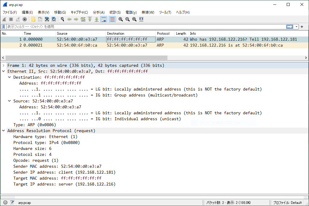
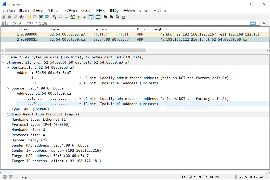
arpingコマンドを実行すると、クライアントからサーバにARP requestパケットが送信されます。そして、その応答として、サーバからクライアントにARP replyパケットが送信されます。このときのWiresharkの実行結果を以下に示します。
ARP requestパケット送信時

ARP replyパケット送信時

7 重複検出(-D)

7.1 同じIPアドレスを持ったホストが同一LAN上に存在する場合

192.168.122.216が同一LAN上に存在するかどうかを確認します。応答があることから(★印)、同一LAN上に192.168.122.216が存在することがわかります。

[root@client ~]# arping -D -c 1 -I eth0 192.168.122.216
ARPING 192.168.122.216 from 0.0.0.0 eth0
Unicast reply from 192.168.122.216 [52:54:00:6F:B0:CA]  1.310ms
Sent 1 probes (1 broadcast(s))
Received 1 response(s) ★

7.2 同じIPアドレスを持ったホストが同一LAN上に存在しない場合

192.168.122.100が同一LAN上に存在するかどうかを確認します。応答がないことから(★印)、同一LAN上に192.168.122.100が存在しないことがわかります。

[root@client ~]# arping -D -c 1 -I eth0 192.168.122.100
ARPING 192.168.122.100 from 0.0.0.0 eth0
Sent 1 probes (1 broadcast(s))
Received 0 response(s) ★

8 隣接ホストのARPテーブルを更新する方法(-U)

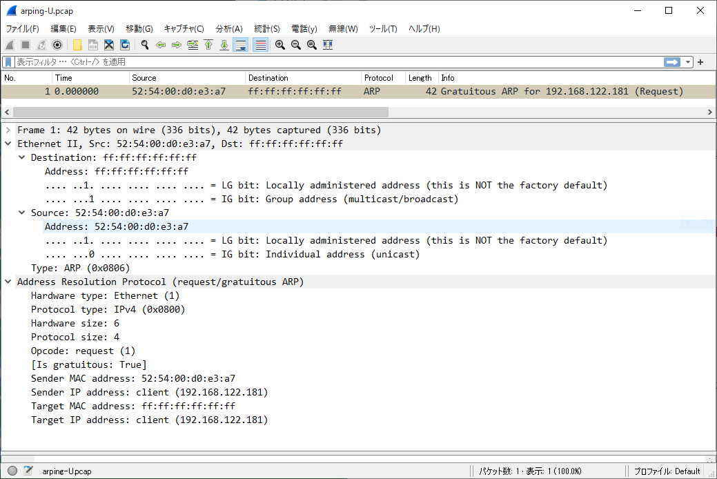
-Uは、Opcodeにrequest(1)を設定して、GARP(Gratuitous ARP)パケットを送信するオプションです。

8.1 ARPテーブル更新のタイミング

通常は以下のように、ARP requestに対してARP replyを受信することでARPテーブルを更新します。

client                                       server
   | IP=x.x.x.x                                 |
   | MAC=yy:yy:yy:yy:yy:yy                      |
   |                                            | ARPテーブル
   |                                            | +-----------------------------+
   |                                            | |    IP   |        MAC        |
   |                                            | +---------+-------------------+
   |                                            | |         |                   |
   |                                            | +-----------------------------+
   |<------------- ARP request -----------------|
   |-------------- ARP reply ------------------>| ARPテーブル更新
   |                                            |
   |                                            | ARPテーブル
   |                                            | +-----------------------------+
   |                                            | |    IP   |        MAC        |
   |                                            | +---------+-------------------+
   |                                            | | x.x.x.x | yy:yy:yy:yy:yy:yy |
   |                                            | +-----------------------------+
   |                                            |

arpingコマンドを使うと、以下のようにしてARPテーブルを更新することができます。

               client                    server
                  | IP=x.x.x.x              |
                  | MAC=yy:yy:yy:yy:yy:yy   | ARPテーブル
                  |                         | +-----------------------------+
                  |                         | |    IP   |        MAC        |
                  |                         | +---------+-------------------+
                  |                         | |         |                   |
                  |                         | +-----------------------------+
                  |                         |
arping -U x.x.x.x |---------- GARP -------->| ARPテーブル更新
                  |       (ARP request)     |
                  |                         | ARPテーブル
                  |                         | +-----------------------------+
                  |                         | |    IP   |        MAC        |
                  |                         | +---------+-------------------+
                  |                         | | x.x.x.x | yy:yy:yy:yy:yy:yy |
                  |                         | +-----------------------------+
                  |                         |

8.2 ARPテーブル更新のための設定

GARPパケット受信時にARPテーブルを更新するためには、arp_acceptを1にする必要があります。arp_acceptについて、ip-sysctl.txtより抜粋したものを以下に示します。

arp_accept - BOOLEAN
    Define behavior for gratuitous ARP frames who's IP is not
    already present in the ARP table:
    0 - don't create new entries in the ARP table
    1 - create new entries in the ARP table

    Both replies and requests type gratuitous arp will trigger the
    ARP table to be updated, if this setting is on.

    If the ARP table already contains the IP address of the
    gratuitous arp frame, the arp table will be updated regardless
    if this setting is on or off.

デフォルトは、以下のように0です。

[root@server ~]# sysctl -n net.ipv4.conf.eth0.arp_accept
0

8.3 動作確認

arp_acceptに1を設定します。

[root@server ~]# sysctl -w net.ipv4.conf.eth0.arp_accept=1
net.ipv4.conf.eth0.arp_accept = 1

ARPテーブルを確認します。

[root@server ~]# ip n
192.168.122.1 dev eth0 lladdr 52:54:00:80:1d:d6 REACHABLE

arpingコマンドを実行します。

[root@client ~]# arping -U -c 1 -I eth0 192.168.122.181
ARPING 192.168.122.181 from 192.168.122.181 eth0
Sent 1 probes (1 broadcast(s))
Received 0 response(s)

ARPテーブルを確認します。クライアントのARPエントリ(IPアドレスMACアドレスの組)が追加されたことがわかります。

[root@server ~]# ip n
192.168.122.1 dev eth0 lladdr 52:54:00:80:1d:d6 REACHABLE
192.168.122.181 dev eth0 lladdr 52:54:00:d0:e3:a7 STALE

arpingコマンド実行時のWiresharkの実行結果を以下に示します。

9 隣接ホストのARPテーブルを更新する方法(-A)

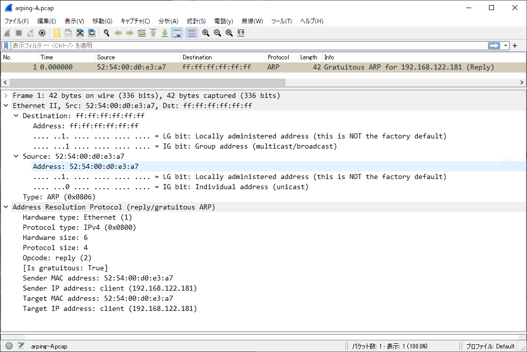
-Aは、Opcodeにreply(2)を設定して、GARPパケットを送信するオプションです。

9.1 ARPテーブル更新のタイミング

arpingコマンドを実行すると、以下のように能動的にARPテーブルを更新することができます。

               client                       server
                  | IP=x.x.x.x                 |
                  | MAC=yy:yy:yy:yy:yy:yy      | ARPテーブル
                  |                            | +-----------------------------+
                  |                            | |    IP   |        MAC        |
                  |                            | +---------+-------------------+
                  |                            | |         |                   |
                  |                            | +-----------------------------+
                  |                            |
arping -A x.x.x.x |------------ GARP --------->| ARPテーブル更新
                  |         (ARP reply)        |
                  |                            | ARPテーブル
                  |                            | +-----------------------------+
                  |                            | |    IP   |        MAC        |
                  |                            | +---------+-------------------+
                  |                            | | x.x.x.x | yy:yy:yy:yy:yy:yy |
                  |                            | +-----------------------------+
                  |                            |

9.2 動作確認

arp_acceptに1を設定します。

[root@server ~]# sysctl -w net.ipv4.conf.eth0.arp_accept=1
net.ipv4.conf.eth0.arp_accept = 1

ARPテーブルを確認します。

[root@server ~]# ip n show
192.168.122.1 dev eth0 lladdr 52:54:00:80:1d:d6 REACHABLE

arpingコマンドを実行します。

[root@client ~]# arping -A -c 1 -I eth0 192.168.122.181

ARPテーブルを確認します。クライアントのARPエントリ(IPアドレスMACアドレスの組)が追加されたことがわかります。

[root@server ~]# ip n show
192.168.122.1 dev eth0 lladdr 52:54:00:80:1d:d6 REACHABLE
192.168.122.181 dev eth0 lladdr 52:54:00:d0:e3:a7 STALE

arpingコマンド実行時のWiresharkの実行結果を以下に示します。

Z 参考情報

私が業務や記事執筆で参考にした書籍を以下のページに記載します。
Linux技術のスキルアップをしよう! - hana_shinのLinux技術ブログ
Gratuitous ARP – Definition and Use Cases – Practical Networking .net

Apacheディレクティブの使い方

1 Apacheディレクティブとは?

ディレクティブとは、Apacheに対するコマンドのことです。Apacheは起動すると、設定ファイル(httpd.conf)を読み込み、そこに記述されているディレクティブに従って動作します。ここでは、いくつかディレクティブの動作確認をしてみます。

2 検証環境

2.1 ネットワーク構成

サーバとクライアントの2台構成です。図中のens33はNICの名前です。

                          192.168.2.0/24
client(ens33) -------------------------------------(ens33) server
        .105                                       .100

2.2 版数

サーバ、クライアントともに、CentOS版数は以下のとおりです。

[root@server ~]# cat /etc/redhat-release
CentOS Linux release 7.9.2009 (Core)

カーネル版数は以下のとおりです。

[root@server ~]# uname -r
3.10.0-1160.el7.x86_64

3 インストール方法

サーバにhttpdパッケージをインストールします。

[root@server ~]# yum -y install httpd

Apacheの版数を確認します。

[root@server ~]# httpd -v
Server version: Apache/2.4.6 (CentOS)
Server built:   Mar 24 2022 14:57:57

httpdサービスを起動します。

[root@server ~]# systemctl start httpd

lsofコマンドを実行します。httpdプロセスは、TCPの80番ポートでListenしていることがわかります。なお、lsofコマンドの使いは、lsofコマンドの使い方 - hana_shinのLinux技術ブログを参照してください。

[root@server ~]# lsof -c httpd -a -i -a -nP
COMMAND  PID   USER   FD   TYPE DEVICE SIZE/OFF NODE NAME
httpd   1650   root    4u  IPv6  28811      0t0  TCP *:80 (LISTEN)
httpd   1651 apache    4u  IPv6  28811      0t0  TCP *:80 (LISTEN)
httpd   1652 apache    4u  IPv6  28811      0t0  TCP *:80 (LISTEN)
httpd   1653 apache    4u  IPv6  28811      0t0  TCP *:80 (LISTEN)
httpd   1654 apache    4u  IPv6  28811      0t0  TCP *:80 (LISTEN)
httpd   1655 apache    4u  IPv6  28811      0t0  TCP *:80 (LISTEN)

httpdプロセスがListenしている80番ポートを解放します。なお、firewall-cmdコマンドの使い方は、firewall-cmdの使い方 - hana_shinのLinux技術ブログを参照してください。

[root@server ~]# firewall-cmd --add-port=80/tcp
success

ポート番号の状態を確認します。80番ポートが解放されたことがわかります。

[root@server ~]# firewall-cmd --list-ports
80/tcp

4 Apacheの動作確認

ブラウザからApacheにアクセスしてみます。本記事では、ブラウザからhttp://192.168.2.100/にアクセスします。

5 Redirect

リクエストを他のサーバに転送するディレクティブです。ここでは、自ホストの/kanteiにアクセスすると、首相官邸のHPにリダイレクトするようにRedirectを設定してみます。

テスト用のディレクトリを作成します。

[root@server ~]# mkdir /kantei

/etc/httpd/conf.d配下にtest.confという名前の定義ファイルを作成します。Redirectディレクティブを使って、/kanteiへのアクセスをhttps://www.kantei.go.jp/にリダイレクトしてみます。

[root@server ~]# vi /etc/httpd/conf.d/test.conf
[root@server ~]# cat /etc/httpd/conf.d/test.conf
Redirect /kantei https://www.kantei.go.jp/

httpdを再起動します。

[root@server ~]# systemctl restart httpd

ブラウザのアドレスバーに、http://192.168.2.100/kanteiと入力します。

/kanteiにアクセスすると、首相官邸のHPにリダイレクトされたことがわかります。

6 Alias

DocumentRootが示すディレクトリに存在しないファイルにアクセスするためのディレクティブです。DocumentRootのデフォルトは、/var/www/htmlです。ここでは、/usr/share/doc/へのアクセスを確認してみます。

[root@server ~]# vi /etc/httpd/conf.d/test.conf
[root@server ~]# cat /etc/httpd/conf.d/test.conf
alias /doc/ "/usr/share/doc/"

<Directory "/usr/share/doc">
  Require all granted
</Directory>

httpdサービスを再起動します。

[root@server ~]# systemctl restart httpd

/usr/share/doc/配下に、下記ファイル(grub.html)がありますので、下記ファイルにブラウザでアクセスしてみます。

[root@server ~]# ls -l /usr/share/doc/grub2-common-2.02/grub.html
-rw-r--r--. 1 root root 503246  7月 29  2020 /usr/share/doc/grub2-common-2.02/grub.html

http://192.168.2.100/doc/grub2-common-2.02/grub.html

7 NameVirtualHost

バーチャルホストとは、1台のホストで複数のWebサーバを提供する機能です。以下の2方式があります。

方式 概要 備考
IPベース ホストに複数のIPアドレスを設定し、各IPアドレス毎にWebサーバを1つ立てる方式
名前ベース 1つのIPアドレスに複数のWebサーバを立てる方式 NameVirtualHostを使う

ここでは、NameVirtualHostを使って、名前ベースのバーチャルホストを試してみます。

7.1 クライアント側の設定

DNSの準備をすると大変なので、かわりにhostsファイルで名前解決をします。

[root@client ~]# vi /etc/hosts
[root@client ~]# cat /etc/hosts
192.168.2.100 www.test1.com
192.168.2.100 www.test2.com

7.2 サーバ側の設定

各Webサーバ用に、DocumentRootで指定するディレクトリを作成します。

[root@server ~]# mkdir -p /var/www/test1/html
[root@server ~]# mkdir -p /var/www/test2/html

各Webサーバのindex.htmlファイルを作成します。

[root@server ~]# echo test1 > /var/www/test1/html/index.html
[root@server ~]# echo test2 > /var/www/test2/html/index.html

/etc/httpd/conf.d配下にtest.confという名前の定義ファイルを作成します。

[root@server ~]# vi /etc/httpd/conf.d/test.conf
[root@server ~]# cat /etc/httpd/conf.d/test.conf
NameVirtualHost 192.168.2.100
<VirtualHost 192.168.2.100>
  DocumentRoot /var/www/test1/html
  ServerName www.test1.com
</VirtualHost>

<VirtualHost 192.168.2.100>
  DocumentRoot /var/www/test2/html
  ServerName www.test2.com
</VirtualHost>

httpdを再起動します。

[root@server ~]# systemctl restart httpd

7.3 動作確認

クライアントから、それぞれのWebサーバにcurlでアクセスしてみます。各Webサーバのindex.htmlの中身が表示されていることがわかります。なお、curlコマンドの使い方は、「curlコマンドの使い方」を参照してください。
www.test1.comでアクセスすると、test1が表示されることがわかります。

[root@client ~]# curl http://www.test1.com/index.html
test1

www.test2.comでアクセスすると、test2が表示されることがわかります。

[root@client ~]# curl http://www.test2.com/index.html
test2

8 DirectoryIndex

Webクライアントからのリクエストがあった時、ファイル名を指定せずディレクトリだけ指定する時があります。ファイル名が省略された場合にどのファイルを返すのかを指定するディレクティブです。Webサーバは、DirectoryIndexで定義されたファイル名を左から右に向かって調べ、最初に見つけたファイル名をクライアントに返します。

8.1 事前準備

定義ファイルをバックアップします。

[root@server ~]# cp /etc/httpd/conf/httpd.conf /etc/httpd/conf/httpd.conf.org

index.htmlとindex.htmの2つのテスト用ファイルを作成します。

[root@server ~]# echo "AAAAA" > /var/www/html/index.html
[root@server ~]# echo "BBBBB" > /var/www/html/index.htm

8.2 動作確認(その1)

httpd.confファイルを修正します。修正内容は以下のとおりです。

[root@server ~]# vi /etc/httpd/conf/httpd.conf
[root@server ~]# diff -Nur /etc/httpd/conf/httpd.conf.org /etc/httpd/conf/httpd.conf
--- /etc/httpd/conf/httpd.conf.org      2022-05-02 22:50:25.676525036 +0900
+++ /etc/httpd/conf/httpd.conf  2022-05-02 22:51:32.933859763 +0900
@@ -162,7 +162,7 @@
 # is requested.
 #
 <IfModule dir_module>
-    DirectoryIndex index.html
+    DirectoryIndex index.html index.htm
 </IfModule>

httpdを再起動します。

[root@server ~]# systemctl restart httpd

ファイル名を指定せず、192.168.2.10にアクセスします。index.htmlの内容が表示されたことがわかります。
http://192.168.2.100/

8.3 動作確認(その2)

DirectoryIndexで定義するファイル名の順序をindex.htm,index.htmlに変更してみます。

[root@server ~]# diff -Nur /etc/httpd/conf/httpd.conf.org /etc/httpd/conf/httpd.conf
--- /etc/httpd/conf/httpd.conf.org      2022-05-02 22:50:25.676525036 +0900
+++ /etc/httpd/conf/httpd.conf  2022-05-02 23:00:41.753986825 +0900
@@ -162,7 +162,7 @@
 # is requested.
 #
 <IfModule dir_module>
-    DirectoryIndex index.html
+    DirectoryIndex index.htm index.html
 </IfModule>

httpdを再起動します。

[root@server ~]# systemctl restart httpd

ファイル名を指定せず、192.168.2.10にアクセスします。index.htmの内容が表示されたことがわかります。
http://192.168.2.100/

9 AuthType

AuthTypeは認証の種類を指定するディレクティブです。指定できる認証として、Basic(基本認証)、Digest(ダイジェスト認証)があります。認証を行う場合、下記ディレクティブを使います。

ディレクティブ 意味
AuthType 認証の種類を指定。Basic(基本認証)、Digest(ダイジェスト認証)がある
AuthName 認可領域の名前を指定
AuthUserFile htpasswdコマンドで作成したパスワードファイルを指定
Require 認証対象のユーザを指定

なお、Requireには次のものがあります。ここでは、Basic認証において、Require valid-userとRequire userの動作確認をしてみます。

種類 意味
Require valid-user 全てのユーザを認証の対象にする
Require user ユーザ名のリスト ユーザ名のリストに指定したユーザだけを認証の対象にする
Require group グループ名 指定したグループだけを認証の対象にする

9.1 事前準備

認証に成功した場合に表示する文字列をindex.htmlに作成します。

[root@server ~]# echo "Basic Authentication" > /var/www/html/index.html

パスワード(.htpasswd)を格納するディレクトリを作成します。なお、パスワードは、DocumentRoot配下に置かないことが推奨されています。

[root@server ~]# mkdir /var/www/passwd/

ユーザを作成します。

[root@server ~]# useradd user1
[root@server ~]# useradd user2

htpasswdコマンドを使って、下記アカウント(ユーザ/パスワード)を作成します。
・user1/pass1
・user2/pass2

user1のパスワードを作成します。なお、htpasswdコマンドの使い方は、htpasswdコマンドの使い方 - hana_shinのLinux技術ブログを参照してください。

[root@server ~]# htpasswd -c /var/www/passwd/.htpasswd user1
New password:
Re-type new password:
Adding password for user user1

user2のパスワードを作成します。

[root@server ~]# htpasswd /var/www/passwd/.htpasswd user2
New password:
Re-type new password:
Adding password for user user2

.htpasswdの中身を確認します。user1とuser2のパスワードが登録されていることがわかります。

[root@server ~]# cat /var/www/passwd/.htpasswd
user1:$apr1$26aDbucD$bJkUtOgEnn51J1dIuK3T9/
user2:$apr1$du3Jg/JX$7beI4hDd8P0lYLXy1x8uy1

9.2 Require valid-userの場合

.htpasswdファイル中の全ユーザを認証対象にするため、Require valid-userと定義します。

[root@server ~]# vi /etc/httpd/conf.d/test.conf
[root@server ~]# cat /etc/httpd/conf.d/test.conf
<Directory "/var/www/html">
  AuthType Basic
  AuthName "Basic Auth"
  AuthUserFile /var/www/passwd/.htpasswd
  Require valid-user
</Directory>

httpdを再起動します。

[root@server ~]# systemctl restart httpd

user1でアクセスします。その時のパスワードはpass1と指定します。期待した文字列(Basic Authentication)が表示されることがわかります。

[root@client ~]# curl -u user1:pass1 http://192.168.2.100/
Basic Authentication

user2でアクセスします。その時のパスワードはpass2と指定します。期待した文字列(Basic Authentication)が表示されることがわかります。

[root@client ~]# curl -u user2:pass2 http://192.168.2.100/
Basic Authentication

9.3 Require userの場合

.htpasswdファイル中のuser1だけを認証対象にするため、Require user user1と定義します。もし、user1とuser2を認証対象にする場合は、Require user user1 user2と定義します。

[root@server ~]# vi /etc/httpd/conf.d/test.conf
[root@server ~]# cat /etc/httpd/conf.d/test.conf
<Directory "/var/www/html">
  AuthType Basic
  AuthName "Basic Auth"
  AuthUserFile /var/www/passwd/.htpasswd
  Require user user1
</Directory>
[root@server ~]# systemctl restart httpd

user1は認証対象なので、Basic認証が成功します。

[root@client ~]# curl -u user1:pass1 http://192.168.2.100/
Basic Authentication

次にuser2でアクセスしてみます。user2は認証対象ではないので、Basic認証が失敗することがわかります。

[root@client ~]# curl -u user2:pass2 http://192.168.2.100/
<!DOCTYPE HTML PUBLIC "-//IETF//DTD HTML 2.0//EN">
<html><head>
<title>401 Unauthorized</title>
</head><body>
<h1>Unauthorized</h1>
<p>This server could not verify that you
are authorized to access the document
requested.  Either you supplied the wrong
credentials (e.g., bad password), or your
browser doesn't understand how to supply
the credentials required.</p>
</body></html>

10 LoadModule

httpd起動時、動的にロードするモジュールを指定するディレクティブです。書式は、次のとおりです。

LoadModule モジュール modules/ファイル名

モジュールは、下記ディレクトリ配下のファイルに定義されています。モジュールをロードしたい場合、LoadModuleの行頭の#を削除してhttpdを再起動することで、モジュールがロードできます。

[root@server ~]# ls -l /etc/httpd/conf.modules.d/
合計 28
-rw-r--r--. 1 root root 3739  1月 14 02:38 00-base.conf
-rw-r--r--. 1 root root  139  1月  8 01:08 00-dav.conf
-rw-r--r--. 1 root root   41  1月  8 01:08 00-lua.conf
-rw-r--r--. 1 root root  742  1月 14 02:38 00-mpm.conf
-rw-r--r--. 1 root root  957  1月 14 02:38 00-proxy.conf
-rw-r--r--. 1 root root   88  1月  8 01:08 00-systemd.conf
-rw-r--r--. 1 root root  451  1月  8 01:08 01-cgi.conf

ファイルは、/usr/lib64/httpd/modulesディレクトリ配下に定義されています。

[root@server ~]# ls -l /usr/lib64/httpd/modules/
合計 2468
-rwxr-xr-x. 1 root root  11232  3月 24 23:58 mod_access_compat.so
-rwxr-xr-x. 1 root root  11176  3月 24 23:58 mod_actions.so
-rwxr-xr-x. 1 root root  15376  3月 24 23:58 mod_alias.so
-snip-

たとえば、Basic認証で使うモジュールは、以下のように定義されています。モジュールはauth_basic_module、ファイル名はmod_auth_basic.soになります。

LoadModule auth_basic_module modules/mod_auth_basic.so

なお、ロードされているモジュールは、以下のようにして確認することができます。詳細は、httpdコマンドの使い方を参照ください。

[root@server ~]# httpd -M
Loaded Modules:
-snip-
 auth_basic_module (shared)
 auth_digest_module (shared)
 authn_anon_module (shared)
 authn_core_module (shared)
-snip-

Z 参考情報

私が業務や記事執筆で参考にした書籍を以下のページに記載します。
Linux技術のスキルアップをしよう! - hana_shinのLinux技術ブログ
udevルールの書き方

1 udevとは?

udevはデバイスファイルを動的に作成、削除する仕組みです。以前は、あらかじめコンピュータに接続する可能性のあるすべてのデバイスのデバイスファイルを作成していましたが、使用しないデバイスファイルを作成するのは無駄なので、udevのように動的にデバイスファイルを作成する仕組みが考案されました。

以下にデバイスファイルを作成するまでの流れを示します。
(1) カーネルがデバイスの追加、削除を検知
(2) /sys配下にデバイスの情報を反映
(3) systemd-udevdにイベント通知(Netlinkでイベント通知)
(4) systemd-udevdは、/sys配下の情報とudevルールを参照
(5) (4)の結果にもとづいて、デバイスファイルを作成

+-----------------------------+
|   udev rule                 |
|     /usr/lib/udev/rules.d   |
|     /etc/udev/rules.d       |
+-----------------------------+
             A
             |
             | (4)参照
             |                                      (5)デバイスファイル作成
+-----------------------------+                       +---------------+
|     systemd-udevd           |---------------------->|               |
+-----------------------------+                       +---------------+
             A            |
             |            | (4)参照
             |            |                           +---------------+
        (3)uevent         +-------------------------->|     /sys      |
             |                                        +---------------+
             |                                                A
             |                                                | (2)デバイス情報作成
             |                                                |
+---------------------------------------------------------------------+
|                                Kernel                               |
+---------------------------------------------------------------------+
                                  A
                                  |
                                  |  (1) カーネルがデバイスの追加、削除を検知

2 検証環境

CentOS版数は以下のとおりです。

[root@server ~]# cat /etc/redhat-release
CentOS Linux release 7.9.2009 (Core)

カーネル版数は以下のとおりです。

[root@server ~]# uname -r
3.10.0-1160.el7.x86_64

3 ルールの概要

3.1 ルールファイルの保存場所

udevのルールファイルは、以下の場所に保存されていいます。本記事では、/etc/udev/rules.d配下にルールを作成します。

パス 概要
/usr/lib/udev/rules.d デフォルトのルールが保存されている場所
/etc/udev/rules.d デフォルトルールをカスタマイズしたルールを置く場所

3.2 ルールファイルの規則

・ルールファイルの拡張子は、.rulesになります。
・ルールファイルの名前は、数字-名前から構成されます。 (例) 50-udev-default.rules
・ルールファイルのルールは、カンマで区切られたkey-valueペアで構成されています。
"=="で検索条件、"="でアクションを指定します。全ての検索条件に一致したら、アクションを実行します。

         検索条件                     アクション
|<------------------------->|  |<---------------->|
XX=="xx", YY=="yy", ZZ=="zz",    AA="aa", BB="bb"

(注) "アクション"という言葉は正式な用語ではないかもしれませんが、ここでは便宜上使用します。

4 ループバックデバイスを使った実験

ここでは、ループバックデバイスを作成して、udevルールの動作確認をしてみます。

ループバックデバイスを作成するためファイルを作成します。ファイルの作り方は、ファイルの作り方 - hana_shinのLinux技術ブログを参照してください。

[root@server ~]# fallocate -l 1G disk1.img

作成したファイルを確認します。

[root@server ~]# ls -l disk1.img
-rw-r--r--. 1 root root 1073741824  4月 27 20:44 disk1.img

loop0を検出したらloggerコマンドを実行するudevルールを作成します。

[root@server ~]# vi /etc/udev/rules.d/10-test.rules
[root@server ~]# cat /etc/udev/rules.d/10-test.rules
KERNEL=="loop0", RUN="/usr/bin/logger loop0"

カーネルからsystemd-udevdへのueventを監視するため、udevadmコマンドを実行します。

[root@server ~]# udevadm monitor -pk
monitor will print the received events for:
KERNEL - the kernel uevent

ログを確認するため、journalctlコマンドを実行します。なお、journalctlコマンドの使い方は、journalctlコマンドの使い方 - hana_shinのLinux技術ブログを参照してください。

[root@server ~]# journalctl -f

ループバックデバイスを作成します。なお、losetupコマンドの使い方は、losetupコマンドの使い方 - hana_shinのLinux技術ブログを参照してください。

[root@server ~]# losetup -f /root/disk1.img

ループバックデバイスを作成すると、カーネルからsystemd-udevdに下記ueventが通知されます。

[root@server ~]# udevadm monitor -pk
monitor will print the received events for:
KERNEL - the kernel uevent

KERNEL[3932.365933] change   /devices/virtual/block/loop0 (block)
ACTION=change
DEVNAME=/dev/loop0
DEVPATH=/devices/virtual/block/loop0
DEVTYPE=disk
MAJOR=7
MINOR=0
SEQNUM=2086
SUBSYSTEM=block

KERNEL[3932.381176] change   /devices/virtual/block/loop0 (block)
ACTION=change
DEVNAME=/dev/loop0
DEVPATH=/devices/virtual/block/loop0
DEVTYPE=disk
MAJOR=7
MINOR=0
SEQNUM=2087
SUBSYSTEM=block

ログを確認すると、loggerコマンドの実行結果が出力されていることがわかります。

[root@server ~]# journalctl -f
-snip-
 4月 27 20:45:46 server root[8999]: loop0
 4月 27 20:45:46 server root[9000]: loop0

ループバックデバイスを確認します。

[root@server ~]# losetup -l
NAME       SIZELIMIT OFFSET AUTOCLEAR RO BACK-FILE
/dev/loop0         0      0         0  0 /root/disk1.img

次の検証のため、ループバックデバイスを削除します。

[root@server ~]# losetup -d /dev/loop0

5 置換(substitution)の使い方

5.1 デバイスパスを表示する方法(%p)

バイスパスは、/sys配下に作成されます。%pはデバイスパスに置換されます。ここで作成するルールは、loopデバイス(*)を検出したら、loggerコマンドを実行します。loggerコマンドで、loopデバイスのデバイスパスを表示します。
(*)loopデバイスのマイナ番号は0,1,2...に一致したものになりま

[root@server ~]# vi /etc/udev/rules.d/10-test.rules
[root@server ~]# cat /etc/udev/rules.d/10-test.rules
KERNEL=="loop*", RUN="/usr/bin/logger %p"

カーネルからsystemd-udevdへのueventを監視するため、udevadmコマンドを実行します。

[root@server ~]# udevadm monitor -pk
monitor will print the received events for:
KERNEL - the kernel uevent

ループバックデバイスを作成します

[root@server ~]# losetup -f /root/disk1.img

ループバックデバイスを作成すると、カーネルからsystemd-udevdに下記ueventが通知されます。

[root@server ~]# udevadm monitor -kp
monitor will print the received events for:
KERNEL - the kernel uevent

KERNEL[6150.972289] change   /devices/virtual/block/loop0 (block)
ACTION=change
DEVNAME=/dev/loop0
DEVPATH=/devices/virtual/block/loop0
DEVTYPE=disk
MAJOR=7
MINOR=0
SEQNUM=2152
SUBSYSTEM=block

KERNEL[6150.984853] change   /devices/virtual/block/loop0 (block)
ACTION=change
DEVNAME=/dev/loop0
DEVPATH=/devices/virtual/block/loop0
DEVTYPE=disk
MAJOR=7
MINOR=0
SEQNUM=2153
SUBSYSTEM=block

ログを確認すると、%pがデバイスパスに置換されたことがわかります。

[root@server ~]# journalctl -f
 4月 27 20:57:25 server root[9029]: /devices/virtual/block/loop0
 4月 27 20:57:25 server root[9030]: /devices/virtual/block/loop0

次の検証のため、ループバックデバイスを削除します。

[root@server ~]# losetup -d /dev/loop0

5.2 デバイス名を表示する方法(%k)

%kはデバイス名に置換するオプションです。

[root@server ~]# vi /etc/udev/rules.d/10-test.rules
[root@server ~]# cat /etc/udev/rules.d/10-test.rules
KERNEL=="loop*", RUN="/usr/bin/logger %k"

ループバックデバイスを作成します

[root@server ~]# losetup -f /root/disk1.img
[root@server ~]# journalctl -f
 4月 27 21:00:08 server root[9044]: loop0
 4月 27 21:00:08 server root[9045]: loop0

次の検証のため、ループバックデバイスを削除します。

[root@server ~]# losetup -d /dev/loop0

5.3 デバイスのプロパティを表示する方法

ここでは、デバイスのプロパティとして、メジャー番号、マイナー番号を表示してみます。

[root@server ~]# vi /etc/udev/rules.d/10-test.rules
[root@server ~]# cat /etc/udev/rules.d/10-test.rules
KERNEL=="loop*", RUN="/usr/bin/logger $env{MAJOR}:$env{MINOR}"

ループバックデバイスを作成します

[root@server ~]# losetup -f /root/disk1.img

ログを確認すると、$env{MAJOR}:$env{MINOR}が、7:0,7:1に置換されたことがわかります。

[root@server ~]# journalctl -f
 4月 27 21:03:07 server root[9069]: 7:0
 4月 27 21:03:07 server root[9070]: 7:0

6 検索条件の使い方

今までは、デバイスの検索条件としてKERNELを使ってきました。検索条件の絞り込みに使えるキーワードは、他にSUBSYSTEM,DRIVER,ENV等があります。詳細は、man udevを参照ください。ここでは、カーネルモジュールの作り方 - hana_shinのLinux技術ブログの「12 デバイスの登録、削除」のプログラムを使って、検索条件の絞り込みを確認してみます。

6.1 SUBSYSTEMを使った絞り込み

[root@server ~]# vi /etc/udev/rules.d/10-test.rules
[root@server ~]# cat /etc/udev/rules.d/10-test.rules
KERNEL=="test_device", SUBSYSTEM=="misc", RUN="/usr/bin/logger %k"

カーネルからsystemd-udevdへのueventを監視するため、udevadmコマンドを実行します。

[root@server ~]# udevadm monitor -kp
monitor will print the received events for:
KERNEL - the kernel uevent

ログを確認するため、journalctlコマンドを実行します。

[root@server ~]# journalctl -f

モジュールをロードします。

[root@server modules]# insmod test.ko

udevadmコマンドを実行すると、testモジュールの情報を確認することができます。

[root@server ~]# udevadm monitor -kp
monitor will print the received events for:
KERNEL - the kernel uevent

KERNEL[4958.602017] add      /module/test (module)
ACTION=add
DEVPATH=/module/test
SEQNUM=2148
SUBSYSTEM=module

KERNEL[4958.602323] add      /devices/virtual/misc/test_device (misc)
ACTION=add
DEVNAME=/dev/test_device
DEVPATH=/devices/virtual/misc/test_device
MAJOR=10
MINOR=58
SEQNUM=2149
SUBSYSTEM=misc

ログを確認します。

[root@server ~]# journalctl -f
 4月 27 21:11:04 server root[9667]: test_device

次の検証のため、モジュールをアンロードします。

[root@server modules]# rmmod test

次の検証のため、ループバックデバイスを削除します。

[root@server ~]# losetup -d /dev/loop0

6.2 ENVを使った絞り込み

[root@server ~]# vi /etc/udev/rules.d/10-test.rules
[root@server ~]# cat /etc/udev/rules.d/10-test.rules
KERNEL=="test_device", SUBSYSTEM=="misc", ENV{MAJOR}=="10", ENV{MINOR}=="55", RUN="/usr/bin/logger %k"

7 アクションの使い方

7.1 OWNER,GROUP,MODEの使い方

バイスファイルにオーナ、グループ、パーミッションを設定することができます。ここでは、test_deviceを検出したら、デバイスファイルのパーミッションを0644に設定してみます。

[root@server ~]# vi /etc/udev/rules.d/10-test.rules
[root@server ~]# cat /etc/udev/rules.d/10-test.rules
KERNEL=="test_device", MODE="0644", RUN="/usr/bin/logger %k"

テスト用のモジュールをロードします。

[root@server modules]# insmod test.ko
[root@server ~]# journalctl -f
 4月 27 21:28:18 server kernel: Device registered!
 4月 27 21:28:18 server root[9717]: test_device

バイスファイルのパーミッションを確認します。パーミッションが644であることがわかります。

[root@server ~]# ls -l /dev/test_device
crw-r--r--. 1 root root 10, 57  4月 27 21:28 /dev/test_device

7.2 NAMEの使い方

br0ならtest-br0,br1ならtest-br1という名前のデバイスファイルを作成するルールを作成します。

[root@server ~]# vi /etc/udev/rules.d/10-test.rules
[root@server ~]# cat /etc/udev/rules.d/10-test.rules
KERNEL=="br*", NAME="test-br%n"

br0という名前のブリッジデバイスを作成します。

[root@server ~]# ip link add br0 type bridge

作成したブリッジを確認します。デバイス名がbr0ではなく、test-br0になっていることがわかります。

[root@server ~]# ip l
-snip-
5: test-br0: <BROADCAST,MULTICAST> mtu 1500 qdisc noop state DOWN mode DEFAULT group default qlen 1000
    link/ether 4e:3f:9e:fe:a5:c6 brd ff:ff:ff:ff:ff:ff

ブリッジデバイス作成時のカーネルからsystemd-udevdへのイベントは以下のようになります。

[root@server ~]# udevadm monitor -kp
monitor will print the received events for:
KERNEL - the kernel uevent

KERNEL[4583.714316] add      /devices/virtual/net/br0 (net)
ACTION=add
DEVPATH=/devices/virtual/net/br0
DEVTYPE=bridge
IFINDEX=9
INTERFACE=br0
SEQNUM=2130
SUBSYSTEM=net

KERNEL[4583.714373] add      /devices/virtual/net/br0/queues/rx-0 (queues)
ACTION=add
DEVPATH=/devices/virtual/net/br0/queues/rx-0
SEQNUM=2131
SUBSYSTEM=queues

KERNEL[4583.714398] add      /devices/virtual/net/br0/queues/tx-0 (queues)
ACTION=add
DEVPATH=/devices/virtual/net/br0/queues/tx-0
SEQNUM=2132
SUBSYSTEM=queues

KERNEL[4583.719449] move     /devices/virtual/net/test-br0 (net)
ACTION=move
DEVPATH=/devices/virtual/net/test-br0
DEVPATH_OLD=/devices/virtual/net/br0
DEVTYPE=bridge
IFINDEX=9
INTERFACE=test-br0
SEQNUM=2133
SUBSYSTEM=net

tsharkコマンドの使い方

1 tsharkコマンドとは?

tsharkは、WiresharkCLI(Command Line Interface)版です。tcpdumpよりtsharkの方がより細かな条件を指定してパケットの絞り込みができます。私自身は、tsharkの方が使い勝手が良いとかんじました。使用目的によって使い分けるとよいと思います。

なお、tcpdumpについては、以下の記事を参照ください。
tcpdumpの使い方(基本編) - hana_shinのLinux技術ブログ
tcpdumpの使い方(パケットファイルの切り替え方法) - hana_shinのLinux技術ブログ

2 検証環境

2.1 ネットワーク構成

サーバとクライアントの2台構成です。図中のeth0はNICの名前です。

                          192.168.122.0/24
client(eth0) --------------------------------------------(eth0) server
           .181                                         .216

2.2 版数

サーバ、クライアントともに下記版数です。

[root@server ~]# cat /etc/redhat-release
CentOS Linux release 7.9.2009 (Core)

3 インストール方法

サーバにwiresharkパッケージをインストールします。

[root@server ~]# yum -y install wireshark

版数を確認します。

[root@server ~]# tshark -v
TShark 1.10.14 (Git Rev Unknown from unknown)
-snip-

4 オプション一覧

オプションは以下のとおりです。

[root@server ~]# tshark -h
TShark 1.10.14 (Git Rev Unknown from unknown)
Dump and analyze network traffic.
See http://www.wireshark.org for more information.

Copyright 1998-2015 Gerald Combs <gerald@wireshark.org> and contributors.
This is free software; see the source for copying conditions. There is NO
warranty; not even for MERCHANTABILITY or FITNESS FOR A PARTICULAR PURPOSE.

Usage: tshark [options] ...

Capture interface:
  -i <interface>           name or idx of interface (def: first non-loopback)
  -f <capture filter>      packet filter in libpcap filter syntax
  -s <snaplen>             packet snapshot length (def: 262144)
  -p                       don't capture in promiscuous mode
  -I                       capture in monitor mode, if available
  -B <buffer size>         size of kernel buffer (def: 4MB)
  -y <link type>           link layer type (def: first appropriate)
  -D                       print list of interfaces and exit
  -L                       print list of link-layer types of iface and exit

Capture stop conditions:
  -c <packet count>        stop after n packets (def: infinite)
  -a <autostop cond.> ...  duration:NUM - stop after NUM seconds
                           filesize:NUM - stop this file after NUM KB
                              files:NUM - stop after NUM files
Capture output:
  -b <ringbuffer opt.> ... duration:NUM - switch to next file after NUM secs
                           filesize:NUM - switch to next file after NUM KB
                              files:NUM - ringbuffer: replace after NUM files
Input file:
  -r <infile>              set the filename to read from (no stdin!)

Processing:
  -2                       perform a two-pass analysis
  -R <read filter>         packet Read filter in Wireshark display filter syntax
  -Y <display filter>      packet displaY filter in Wireshark display filter syntax
  -n                       disable all name resolutions (def: all enabled)
  -N <name resolve flags>  enable specific name resolution(s): "mnNtC"
  -d <layer_type>==<selector>,<decode_as_protocol> ...
                           "Decode As", see the man page for details
                           Example: tcp.port==8888,http
  -H <hosts file>          read a list of entries from a hosts file, which will
                           then be written to a capture file. (Implies -W n)
Output:
  -w <outfile|->           write packets to a pcap-format file named "outfile"
                           (or to the standard output for "-")
  -C <config profile>      start with specified configuration profile
  -F <output file type>    set the output file type, default is pcapng
                           an empty "-F" option will list the file types
  -V                       add output of packet tree        (Packet Details)
  -O <protocols>           Only show packet details of these protocols, comma
                           separated
  -P                       print packet summary even when writing to a file
  -S <separator>           the line separator to print between packets
  -x                       add output of hex and ASCII dump (Packet Bytes)
  -T pdml|ps|psml|text|fields
                           format of text output (def: text)
  -e <field>               field to print if -Tfields selected (e.g. tcp.port, col.Info);
                           this option can be repeated to print multiple fields
  -E<fieldsoption>=<value> set options for output when -Tfields selected:
     header=y|n            switch headers on and off
     separator=/t|/s|<char> select tab, space, printable character as separator
     occurrence=f|l|a      print first, last or all occurrences of each field
     aggregator=,|/s|<char> select comma, space, printable character as
                           aggregator
     quote=d|s|n           select double, single, no quotes for values
  -t a|ad|d|dd|e|r|u|ud    output format of time stamps (def: r: rel. to first)
  -u s|hms                 output format of seconds (def: s: seconds)
  -l                       flush standard output after each packet
  -q                       be more quiet on stdout (e.g. when using statistics)
  -Q                       only log true errors to stderr (quieter than -q)
  -g                       enable group read access on the output file(s)
  -W n                     Save extra information in the file, if supported.
                           n = write network address resolution information
  -X <key>:<value>         eXtension options, see the man page for details
  -z <statistics>          various statistics, see the man page for details

Miscellaneous:
  -h                       display this help and exit
  -v                       display version info and exit
  -o <name>:<value> ...    override preference setting
  -K <keytab>              keytab file to use for kerberos decryption
  -G [report]              dump one of several available reports and exit
                           default report="fields"
                           use "-G ?" for more help

5 事前準備(一般ユーザの作成)

rootユーザでtsharkを実行すると、下記メッセージが出力されるので、本記事では一般ユーザでtsharkを実行します。

[root@server ~]# tshark -i eth0 -n -Y 'tcp.port==11111'
Running as user "root" and group "root". This could be dangerous.
Capturing on 'eth0'

user1を追加します。なお、ユーザの追加、削除は、useradd/groupaddコマンドの使い方 - hana_shinのLinux技術ブログを参照してください。

[root@server ~]# useradd user1

idコマンドを実行して、user1の各種IDを確認します。

[root@server ~]# id user1
uid=1000(user1) gid=1000(user1) groups=1000(user1)

user1のセカンダリーグループにwiresharkグループを追加します。

[root@server ~]# usermod -a -G wireshark user1

idコマンドを実行します。user1のセカンダリーグループにwiresharkグループが追加されたことがわかります。

[root@server ~]# id user1
uid=1000(user1) gid=1000(user1) groups=1000(user1),995(wireshark)

一般ユーザに切り替えます。

[root@server ~]# su - user1

一般ユーザで実行すると、以下のように警告が表示されなくなります。

[user1@server ~]$ tshark -i eth0 -n -Y 'tcp.port==11111'
Capturing on 'eth0'

なお、user1からwiresharkグループの削除は、以下のようにroot権限で実行します。

[root@server ~]# usermod -a -G wireshark user1

6 インタフェース一覧を表示する方法(-D)

-Dはパケットキャプチャに指定できるインタフェース一覧を表示するオプションです。

[user1@server ~]$ tshark -D
1. eth0
2. nflog
3. nfqueue
4. any
5. lo (Loopback)

7 Capture vs Display Filters

tsharkには、2つのフィルタがあります。本記事では、大部分の説明にDisplayフィルタを使います。

フィルタ名 概要 オプション 書式 フィルタの例 参考情報
Captureフィルタ 採取するパケット量を減らすために使用する。BPF syntaxに従う。tcpdumpでも使うことができるフィルタ -f tshark -f "Capture Filter" host 192.168.1.0 Tshark | Capture Filters
Display フィルタ Captureフィルタに比べ、詳細な条件でパケットの指定ができる -Y tshark -Y 'Display filter' tcp.flags.syn==1 Tshark | Display Filters

8 TCPパケットを絞り込む方法

以下の図はTCPコネクション確立時のパケットのやり取りを示したものです。この手順は、3 Way Handshakeと呼ばれています。

 client                                             server
   |                                                   |
   |                        SYN                        |
   |-------------------------------------------------->|
   |                        SYN+ACK                    |
   |<--------------------------------------------------|
   |                        ACK                        |
   |-------------------------------------------------->|
   |                                                   |

8.1 ポート番号で絞り込む方法

テスト用に使用するTCPの11111番ポートを解放します。なお、firewall-cmdコマンドの使い方は、firewall-cmdの使い方 - hana_shinのLinux技術ブログを参照してください。

[root@server ~]# firewall-cmd --add-port=11111/tcp
success

次に、一般ユーザに切り替えてtsharkコマンドを実行します。表示するパケットをTCPの11111番ポートに絞り込んでみます。

[user1@server ~]$ tshark -i eth0 -n -Y 'tcp.port==11111'
Capturing on 'eth0'

もう1つターミナルを開きます。そして、ncコマンドを実行します。なお、ncコマンドのインストール方法、使い方は、ncコマンドの使い方(ネットワーク実験の幅が広がるなぁ~) - hana_shinのLinux技術ブログを参照してください。

[user1@server ~]$ nc -kl 11111

lsofコマンドを実行します。ncプロセスがTCPの11111番ポートでListenしていることがわかります。なお、lsofコマンドのインストール方法、使い方はlsofコマンドの使い方 - hana_shinのLinux技術ブログを参照してください。

[user1@server ~]$ lsof -c nc -a -i -a -nP
COMMAND  PID  USER   FD   TYPE DEVICE SIZE/OFF NODE NAME
nc      2723 user1    3u  IPv6  47150      0t0  TCP *:11111 (LISTEN)
nc      2723 user1    4u  IPv4  47151      0t0  TCP *:11111 (LISTEN)

クライアントでncコマンドを実行します。ncコマンドを実行すると、サーバとクライアントの間で3 Way Handshakeが実行され、TCPコネクションが確立されます。

[root@client ~]# nc 192.168.122.216 11111

tsharkコマンドの実行結果を確認すると、TCPの11111番ポートのパケットが表示されていることがわかります。

[user1@server ~]$ tshark -i eth0 -n -Y 'tcp.port==11111'
Capturing on 'eth0'
  3 2.193618268 192.168.122.181 -> 192.168.122.216 TCP 74 50130 > 11111 [SYN] Seq=0 Win=29200 Len=0 MSS=1460 SACK_PERM=1 TSval=1093318 TSecr=0 WS=128
  4 2.193656226 192.168.122.216 -> 192.168.122.181 TCP 74 11111 > 50130 [SYN, ACK] Seq=0 Ack=1 Win=28960 Len=0 MSS=1460 SACK_PERM=1 TSval=1089335 TSecr=1093318 WS=128
  5 2.194571409 192.168.122.181 -> 192.168.122.216 TCP 66 50130 > 11111 [ACK] Seq=1 Ack=1 Win=29312 Len=0 TSval=1093319 TSecr=1089335

8.2 SYNフラグで絞り込む方法

SYNパケットのみを表示するようにしてみます。SYNパケットは、TCPヘッダのSYNフラグが1、ACKフラグが0のパケットになります。

[user1@server ~]$ tshark -i eth0 -n -Y 'tcp.flags.syn==1 and tcp.flags.ack==0'
Capturing on 'eth0'

サーバでncコマンドを実行します。

[user1@server ~]$ nc -kl 11111

クライアントでncコマンドを実行します。

[root@client ~]# nc 192.168.122.216 11111

SYNパケットのみが表示されていることがわかります。

[user1@server ~]$ tshark -i eth0 -n -Y 'tcp.flags.syn==1 and tcp.flags.ack==0'
Capturing on 'eth0'
 12 21.603307093 192.168.122.181 -> 192.168.122.216 TCP 74 50132 > 11111 [SYN] Seq=0 Win=29200 Len=0 MSS=1460 SACK_PERM=1 TSval=1140726 TSecr=0 WS=128

8.3 SYN+ACKフラグで絞り込む方法

SYN+ACKパケットのみ表示するようにしてみます。SYN+ACKパケットは、TCPヘッダのSYNフラグが1、ACKフラグが1のパケットになります。

[user1@server ~]$ tshark -i eth0 -n -Y 'tcp.flags.syn==1 and tcp.flags.ack==1'
Capturing on 'eth0'

サーバでncコマンドを実行します。

[user1@server ~]$ nc -kl 11111

クライアントでncコマンドを実行します。

[root@client ~]# nc 192.168.122.216 11111

SYN+ACKパケットのみ表示されていることがわかります。

[user1@server ~]$ tshark -i eth0 -n -Y 'tcp.flags.syn==1 and tcp.flags.ack==1'
Capturing on 'eth0'
 15 13.824986323 192.168.122.216 -> 192.168.122.181 TCP 74 11111 > 50134 [SYN, ACK] Seq=0 Ack=1 Win=28960 Len=0 MSS=1460 SACK_PERM=1 TSval=1173489 TSecr=1177472 WS=128

9 ARPパケットを絞り込む方法

クライアントでarpingコマンドを実行すると、ARP requestがサーバに送信されます。そして、その応答として、ARP replyがサーバからクライアントに送信されます。9.1でARP request 、9.2でARP replyをキャプチしてみます。arpingコマンドの使い方は、arpingコマンドの使い方 - hana_shinのLinux技術ブログを参照してください。

 client                                             server
   |                                                   |
   |                      ARP request                  |
   |-------------------------------------------------->|
   |                      ARP reply                    |
   |<--------------------------------------------------|
   |                                                   |

9.1 ARP requestを絞り込む方法(arp.opcode==1)

ARP requestのみを表示するようにしてみます。

[user1@server ~]$ tshark -i eth0 -Y 'arp.opcode==1'
Capturing on 'eth0'

クライアントでarpingコマンドを実行して、ARP requestをサーバに送信します。

[root@client ~]# arping -c 1 -I eth0 192.168.122.216
ARPING 192.168.122.216 from 192.168.122.181 eth0
Unicast reply from 192.168.122.216 [52:54:00:6F:B0:CA]  1.635ms
Sent 1 probes (1 broadcast(s))
Received 1 response(s)

ARP requestが表示されていることがわかります。

[user1@server ~]$ tshark -i eth0 -Y 'arp.opcode==1'
Capturing on 'eth0'
 16 13.804617952 RealtekU_d0:e3:a7 -> Broadcast    ARP 42 Who has 192.168.122.216?  Tell 192.168.122.181

9.2 ARP replyパケットを絞り込む方法(arp.opcode==2)

ARP replyのみを表示するようにしてみます。

[user1@server ~]$ tshark -i eth0 -Y 'arp.opcode==2'
Capturing on 'eth0'

クライアントでarpingコマンドを実行して、ARP requestをサーバに送信します。

[root@client ~]# arping -c 1 -I eth0 192.168.122.216
ARPING 192.168.122.216 from 192.168.122.181 eth0
Unicast reply from 192.168.122.216 [52:54:00:6F:B0:CA]  2.087ms
Sent 1 probes (1 broadcast(s))次はキャプチャ1にパケットを書き
Received 1 response(s)

ARP replyが表示されていることがわかります。

[user1@server ~]$ tshark -i eth0 -Y 'arp.opcode==2'
Capturing on 'eth0'
  8 10.417888942 RealtekU_6f:b0:ca -> RealtekU_d0:e3:a7 ARP 42 192.168.122.216 is at 52:54:00:6f:b0:ca

10 ICMPパケットを絞り込む方法

10.1 ICMP Echo requestを絞り込む方法(icmp.type==8)

ICMP Echo requestのみを表示するようにしてみます。

[user1@server ~]$ tshark -i eth0 -Y 'icmp.type==8'
Capturing on 'eth0'

クライアントでpingを実行します。宛先にサーバを指定します。なお、pingコマンドの使い方は、pingコマンドの使い方 - hana_shinのLinux技術ブログを参照してください。

[root@client ~]# ping -c 1 192.168.122.216

ICMP Echo requestを確認することができます。

[user1@server ~]$ tshark -i eth0 -Y 'icmp.type==8'
Capturing on 'eth0'
  6 8.660830070 192.168.122.181 -> 192.168.122.216 ICMP 98 Echo (ping) request  id=0x05b4, seq=1/256, ttl=64

10.2 ICMP Echo replyを絞り込む方法(icmp.type==0)

ICMP Echo replyのみを表示するようにしてみます。

[user1@server ~]$ tshark -i eth0 -Y 'icmp.type==0'
Capturing on 'eth0

クライアントでpingを実行します。宛先にサーバを指定します。

[root@client ~]# ping -c 1 192.168.122.216

ICMP Echo replyが表示されていることがわかります。

[user1@server ~]$ tshark -i eth0 -Y 'icmp.type==0'
Capturing on 'eth0'
  7 9.499034114 192.168.122.216 -> 192.168.122.181 ICMP 98 Echo (ping) reply    id=0x05b5, seq=1/256, ttl=64 (request in 6)

10.3 ICMP Echo request/replyを表示する方法

ICMP Echo request /replyのみを表示するようにしてみます。

[user1@server ~]$ tshark -i eth0 -Y 'icmp.type==0 or icmp.type==8'
Capturing on 'eth0'

クライアントでpingを実行します。宛先にサーバを指定します。

[root@client ~]# ping -c 1 192.168.122.216

ICMP Echo request/replyを確認することができます。

[user1@server ~]$ tshark -i eth0 -Y 'icmp.type==0 or icmp.type==8'
Capturing on 'eth0'
  8 13.014091703 192.168.122.181 -> 192.168.122.216 ICMP 98 Echo (ping) request  id=0x05b6, seq=1/256, ttl=64
  9 13.014176543 192.168.122.216 -> 192.168.122.181 ICMP 98 Echo (ping) reply    id=0x05b6, seq=1/256, ttl=64 (request in 8)

11 DNSパケットを絞り込む方法

DNSパケットのみを表示してみます。DNSパケットはUDPの53番ポートを使用します。

[user1@server ~]$ tshark -i eth0 -n -Y 'udp.port==53'
Capturing on 'eth0'

サーバでdigコマンドを実行します。なお、digコマンドのインストール方法、使い方はdigコマンドの使い方 - hana_shinのLinux技術ブログを参照してください。

[user1@server ~]$ dig ntp.nict.jp +short
133.243.238.243
133.243.238.244
133.243.238.163
61.205.120.130
133.243.238.164

DNS query/responseパケットを確認することができます。

[user1@server ~]$ tshark -i eth0 -n -Y 'udp.port==53'
Capturing on 'eth0'
 20 15.622015640 192.168.122.216 -> 192.168.122.1 DNS 82 Standard query 0x9cf9  A ntp.nict.jp
 21 15.633936844 192.168.122.1 -> 192.168.122.216 DNS 162 Standard query response 0x9cf9  A 133.243.238.243 A 133.243.238.244 A 133.243.238.163 A 61.205.120.130 A 133.243.238.164

12 キャプチャファイルを自動で切り替える方法(-b)

-bは、パケットを保存しているキャプチャファイルを切り替えるオプションです。たとえば、キャプチャファイルのサイズが大きくなったので、別のキャプチャファイルに自動的に切り替える、といったことができます。

12.1 時間で切り替える方法(duration:NUM)

3秒経過すると、次のキャプチャファイルにパケットを書き込むようにします。

[user1@server ~]$ tshark -b duration:3 -f 'icmp' -w test.pcap
Capturing on 'eth0'

tsharkコマンド実行中、キャプチャファイルを確認すると、3秒毎に新しいキャプチャファイルが作成されていることがわかります。

[user1@server ~]$ ls -l
合計 12
-rw-------. 1 user1 user1 200  4月 27 11:20 test_00001_20220427112017.pcap
-rw-------. 1 user1 user1 200  4月 27 11:20 test_00002_20220427112020.pcap
-rw-------. 1 user1 user1 200  4月 27 11:20 test_00003_20220427112023.pcap
-snip-

12.2 ファイルサイズで切り替える方法(filesize:NUM)

キャプチャファイルのサイズが1(KB)になると、次のキャプチャファイルにパケットを書き込むようにします。

[user1@server ~]$ tshark -b filesize:1 -f 'icmp' -w test.pcap
Capturing on 'eth0'

クライアントでpingを実行します。宛先にサーバを指定します。

[root@client ~]# ping 192.168.122.216

キャプチャファイルのサイズを確認します。およそ1024(byte)単位でキャプチャファイルが作成されていることがわかります。キャプチャファイルのサイズは多少の誤差が生じるようです。

[user1@server ~]$ ls -l
合計 28
-rw-------. 1 user1 user1 1124  4月 27 11:24 test_00001_20220427112346.pcap
-rw-------. 1 user1 user1 1124  4月 27 11:24 test_00002_20220427112401.pcap
-rw-------. 1 user1 user1 1124  4月 27 11:24 test_00003_20220427112404.pcap
-snip-

12.3 リングバッファのように使う方法(files:NUM)

NUMに2を指定した場合、キャプチャファイル1=>キャプチャファイル2と書き込みをしたあと、次はキャプチャファイル1にパケットを書き込みます。なお、本オプションはdurationまたはfilesizeオプションと一緒に使う必要があります。

ここでは、キャプチャファイルの数を2、キャプチャファイルのサイズを1KBに指定してみます。

[user1@server ~]$ tshark -b files:2 -b filesize:1 -f 'icmp' -w test
Capturing on 'eth0'

クライアントでpingを実行します。宛先にサーバを指定します。

[root@client ~]# ping 192.168.122.216

キャプチャファイルの数とサイズを確認します。15秒と48秒に作成されたキャプチャファイルが2つあることがわかります。48秒に作成されたキャプチャファイルのサイズは、332Byteであることがわかります。

[user1@server ~]$ ls -l
合計 8
-rw-------. 1 user1 user1 1124  4月 27 11:46 test_00001_20220427114615
-rw-------. 1 user1 user1  332  4月 27 11:46 test_00002_20220427114648

キャプチャファイルの数とサイズを確認します。キャプチャファイルの数は2個のままです。15秒に作成されたキャプチャファイルが削除され、新たに51秒にキャプチャファイルが作成されていることがわかります。

[user1@server ~]$ ls -l
合計 8
-rw-------. 1 user1 user1 1124  4月 27 11:46 test_00002_20220427114648
-rw-------. 1 user1 user1  200  4月 27 11:46 test_00003_20220427114651

キャプチャファイルの数とサイズを確認します。キャプチャファイルの数は2個のままです。48秒に作成されたキャプチャファイルが削除され、新たに55秒にキャプチャファイルが作成されていることがわかります。

[user1@server ~]$ ls -l
合計 8
-rw-------. 1 user1 user1 1124  4月 27 11:46 test_00003_20220427114651
-rw-------. 1 user1 user1  332  4月 27 11:46 test_00004_20220427114655

13 出力を自動で停止する方法(-a)

キャプチャファイルの保存はDisplayフィルタではできないようなので、ここではCaptureフィルタを使います。

13.1 時間を指定する方法

指定した時間が経過したら、tsharkコマンドを終了します。ここでは、出力時間を3秒に指定してみます。

[user1@server ~]$ tshark -a duration:3 -f 'icmp'
Capturing on 'eth0'
  1 0.000000000 192.168.122.181 -> 192.168.122.216 ICMP 98 Echo (ping) request  id=0x05fd, seq=124/31744, ttl=64
  2 0.000047753 192.168.122.216 -> 192.168.122.181 ICMP 98 Echo (ping) reply    id=0x05fd, seq=124/31744, ttl=64 (request in 1)
  3 1.002224142 192.168.122.181 -> 192.168.122.216 ICMP 98 Echo (ping) request  id=0x05fd, seq=125/32000, ttl=64
  4 1.002255861 192.168.122.216 -> 192.168.122.181 ICMP 98 Echo (ping) reply    id=0x05fd, seq=125/32000, ttl=64 (request in 3)
  5 2.003997827 192.168.122.181 -> 192.168.122.216 ICMP 98 Echo (ping) request  id=0x05fd, seq=126/32256, ttl=64
  6 2.004034436 192.168.122.216 -> 192.168.122.181 ICMP 98 Echo (ping) reply    id=0x05fd, seq=126/32256, ttl=64 (request in 5)
6 packets captured

13.2 ファイルサイズを指定する方法(filesize:NUM)

キャプチャファイルが指定したサイズ(1K)に達すると、tsharkコマンドが終了するようにしてみます。

[user1@server ~]$ tshark -a filesize:1 -f 'icmp' -w test.pcap
Capturing on 'eth0'

クライアントでpingを実行します。宛先にサーバを指定します。

[root@client ~]# ping 192.168.122.216

キャプチャファイルのサイズが1Kに達すると、tsharkコマンドが自動的に終了します。

[user1@server ~]$ tshark -a filesize:1 -f 'icmp' -w test.pcap
Capturing on 'eth0'
7

キャプチャファイルのサイズを確認します。ファイルサイズがおよそ1Kであることがわかります。

[user1@server ~]$ ls -l test.pcap
-rw-------. 1 user1 user1 1232  4月 27 15:32 test.pcap

14 特定のフィールドを表示する方法(-T fields -e)

フレーム番号、IPアドレスTCPポート番号を出力するようにしてみます。

[user1@server ~]$ tshark -i eth0 -Y 'tcp.port==11111' -T fields -e frame.number -e ip.addr -e tcp.port
Capturing on 'eth0'

サーバでncコマンドを実行します。

[user1@server ~]$ nc -kl 11111

クライアントでpingを実行します。宛先にサーバを指定します。

[root@client ~]# nc 192.168.122.216 11111

左から順に、フレーム番号、IPアドレスTCPポート番号が出力されていることがわかります。

[user1@server ~]$ tshark -i eth0 -Y 'tcp.port==11111' -T fields -e frame.number -e ip.addr -e tcp.port
Capturing on 'eth0'
29      192.168.122.181,192.168.122.216 50136,11111
30      192.168.122.216,192.168.122.181 11111,50136
31      192.168.122.181,192.168.122.216 50136,11111

15 プロミスキャスモード(-p)

NICをプロミスキャスモードにすると、宛先MACアドレスが自身以外のパケットもキャプチャしてしまいます。-Pを指定してNICがプロミスキャスモードにならないようにすると、宛先MACアドレスが自分宛のパケットだけをキャプチャするようになります。
プロミスキャスモードについては、以下の記事を参照してください。
tcpdumpの使い方(基本編) - hana_shinのLinux技術ブログの「6 プロミスキャス・モードへの移行を抑止する方法(-p)」を参照してください。

16 時刻を表示する方法(-t)

16.1 現在時刻を表示する方法(a)

[user1@server ~]$ tshark -i eth0 -n -Y 'icmp' -t a
Capturing on 'eth0'
 20 09:57:09.241950679 192.168.122.181 -> 192.168.122.216 ICMP 98 Echo (ping) request  id=0x05b9, seq=1/256, ttl=64
 21 09:57:09.241985541 192.168.122.216 -> 192.168.122.181 ICMP 98 Echo (ping) reply    id=0x05b9, seq=1/256, ttl=64 (request in 20)

16.2 UTC時刻を表示する方法(u)

[user1@server ~]$ tshark -i eth0 -n -Y 'icmp' -t u
Capturing on 'eth0'
  2 00:57:27.537284936 192.168.122.181 -> 192.168.122.216 ICMP 98 Echo (ping) request  id=0x05ba, seq=1/256, ttl=64
  3 00:57:27.537320767 192.168.122.216 -> 192.168.122.181 ICMP 98 Echo (ping) reply    id=0x05ba, seq=1/256, ttl=64 (request in 2)

16.3 エポックタイムを表示する方法(e)

[user1@server ~]$ tshark -i eth0 -n -Y 'icmp' -t e
Capturing on 'eth0'
  1 1651021060.745605918 192.168.122.181 -> 192.168.122.216 ICMP 98 Echo (ping) request  id=0x05bb, seq=1/256, ttl=64
  2 1651021060.745657363 192.168.122.216 -> 192.168.122.181 ICMP 98 Echo (ping) reply    id=0x05bb, seq=1/256, ttl=64 (request in 1)

17 統計情報の表示方法(-z)

17.1 その1

5秒間隔でICMPの統計情報を表示するようにします。

[user1@server ~]$ tshark -i eth0 -q -z io,stat,5,icmp
Capturing on 'eth0'

クライアントでpingを10回実行します。宛先にサーバを指定します。

[root@client ~]# ping -c 10 192.168.122.216

適当な時間経過したら、Ctrl+Cを押下してtsharkコマンドを終了します。ICMP Echo request/replyあわせて、合計20個表示されていることがわかります。

[user1@server ~]$ tshark -i eth0 -q -z io,stat,5,icmp
Capturing on 'eth0'


^C53 packets captured

==============================================
| IO Statistics                              |
|                                            |
| Interval size: 5 secs                      |
| Col 1: Frames and bytes                    |
|     2: icmp                                |
|--------------------------------------------|
|          |1               |2               |
| Interval | Frames | Bytes | Frames | Bytes |
|--------------------------------------------|
|  0 <>  5 |     13 |  1136 |     10 |   980 |
|  5 <> 10 |     14 |  1168 |     10 |   980 |
| 10 <> 15 |      5 |   240 |      0 |     0 |
==============================================

17.1 その2

TCPの11111番ポートのパケットだけを統計情報に表示するようにしてみます。

[user1@server ~]$ tshark -i eth0 -f "tcp port 11111" -q -z io,stat,5,tcp
Capturing on 'eth0'

サーバでncコマンドを実行します。

[user1@server ~]$ nc -kl 11111

クライアントでncコマンドを実行します。

[root@client ~]# nc 192.168.122.216 11111

TCPコネクション確立時にやり取りする3個のパケットが統計情報に表示されていることがわかります。

[user1@server ~]$ tshark -i eth0 -f "tcp port 11111" -q -z io,stat,5,tcp
Capturing on 'eth0'
^C3 packets captured

====================================================
| IO Statistics                                    |
|                                                  |
| Interval size: 0.001 secs (dur)                  |
| Col 1: Frames and bytes                          |
|     2: tcp                                       |
|--------------------------------------------------|
|                |1               |2               |
| Interval       | Frames | Bytes | Frames | Bytes |
|--------------------------------------------------|
| 0.000 <> 0.001 |      3 |   214 |      3 |   214 |
====================================================
[user1@server ~]$

18 NetLinkを流れるパケットを表示する方法

NetLinkは、カーネルとユーザー空間のプロセス間で情報をやりとりするために用いられるインタフェースです。NetLinkについては、Netlinkプログラミングの書き方 - hana_shinのLinux技術ブログを参照してください。

nlmonモジュールをロードします。一般ユーザではロードできないので、rootユーザでロードします。

[root@server ~]# modprobe nlmon

ロードしたモジュールを確認します。nlmonモジュールがロードされたことがわかります。

[root@server ~]# lsmod |grep nlmon
nlmon                  12924  0

nlmon0という名前のデバイスを追加します。タイプにはnlmontを指定します。

[root@server ~]# ip link add nlmon0 type nlmon

バイスをアップします。

[root@server ~]# ip link set nlmon0 up

一般ユーザに切り替えます。

[root@server ~]# su - user1

tsharkコマンドを実行します。このときnlmon0デバイスを指定します。

[user1@server ~]$ tshark -i nlmon0
Capturing on 'nlmon0'

もう1つターミナルを開きます。そして、ipコマンドを実行します。

[user1@server ~]$ ip link show dev eth0
2: eth0: <BROADCAST,MULTICAST,UP,LOWER_UP> mtu 1500 qdisc pfifo_fast state UP mode DEFAULT group default qlen 1000
    link/ether 52:54:00:6f:b0:ca brd ff:ff:ff:ff:ff:ff

ipコマンドを実行すると、NetLinkを流れるパケットが確認できます。

[user1@server ~]$ tshark -i nlmon0
Capturing on 'nlmon0'
  1 0.000000000              ->              UNKNOWN 68 WTAP_ENCAP = 0
  2 0.000157466              ->              UNKNOWN 1272 WTAP_ENCAP = 0

Z 参考情報

私が業務や記事執筆で参考にした書籍を以下のページに記載します。
Linux技術のスキルアップをしよう! - hana_shinのLinux技術ブログ

keepalivedの環境構築手順

1 keepalivedとは?

冗長構成のシステムを構築するためのツールです。ここでは、keepalivedを使って、サーバ2台の冗長構成を作成してみます。

2 検証環境

2.1 ネットワーク構成

KVMホストに仮想マシン2台構成です。仮想IPアドレスは192.168.122.100です。また、各サーバの実IPアドレスは以下のとおりです。
・サーバ1の実IPアドレス:192.168.122.216
・サーバ2の実IPアドレス:192.168.122.181

                  仮想IP=192.168.122.100

+--- server1 ---+                     +--- server2 ---+
|  (CentOS7.9)  |                     |  (CentOS7.9)  |
|               |                     |               |
|               |                     |               |
+----- eth0 ----+                     +----- eth0 ----+
        | .216                                |.181
        |                                     |
-------------------------------------------------------
                    192.168.122.0/24

2.2 版数

CentOS版数は、サーバ1、サーバ2ともに下記版数です。

[root@server1 ~]# cat /etc/redhat-release
CentOS Linux release 7.9.2009 (Core)

カーネル版数は以下のとおりです。

[root@server1 ~]# uname  -r
3.10.0-1160.el7.x86_64

3 パッケージのインストール

サーバ1、サーバ2でkeepalivedパッケージをインストールします。

[root@server1 ~]# yum -y install keepalived
[root@server2 ~]# yum -y install keepalived

keepalivedの版数を確認します。

[root@server1 ~]# keepalived --version
Keepalived v1.3.5 (03/19,2017), git commit v1.3.5-6-g6fa32f2
-snip-

サーバの切り替えをhttpdを使って確認するため、httpdパッケージをインストールします。サーバ1、サーバ2でhttpdパッケージをインストールします。

[root@server1 ~]# yum -y install httpd
[root@server2 ~]# yum -y install httpd

4 Netfilterの設定

各サーバのkeepalivedは、お互いが生きているかどうかをマルチキャストパケットを送信しあって監視します。そのため、それぞれのサーバでマルチキャストパケットを送受信できるようにする必要があります。なお、Netfilterの位置づけは、firewall-cmdの使い方 - hana_shinのLinux技術ブログを参照してください。

4.1 サーバ1の設定

224.0.0.18宛てのマルチキャストパケットの受信を許可します。なお、firewall-cmdコマンドの使い方は、firewall-cmdの使い方 - hana_shinのLinux技術ブログを参照してください。

[root@server1 ~]# firewall-cmd --direct --add-rule ipv4 filter INPUT 1 -i eth0 -d 224.0.0.18 -p vrrp -j ACCEPT
success

224.0.0.18宛てのマルチキャストパケットの送信を許可します。

[root@server1 ~]# firewall-cmd --direct --add-rule ipv4 filter OUTPUT 1 -o eth0 -d 224.0.0.18 -p vrrp -j ACCEPT
success

サーバが再起動すると設定が消えるので、設定をパーマネントルールとして保存します。

[root@server1 ~]# firewall-cmd --runtime-to-permanent
success

設定内容を確認します。マルチキャストパケットの送受信を許可するルールが設定されていることがわかります。

[root@server1 ~]# firewall-cmd --direct --get-all-rules
ipv4 filter OUTPUT 1 -o eth0 -d 224.0.0.18 -p vrrp -j ACCEPT
ipv4 filter INPUT 1 -i eth0 -d 224.0.0.18 -p vrrp -j ACCEPT

4.2 サーバ2の設定

224.0.0.18宛てのマルチキャストパケットの受信を許可します。

[root@server2 ~]# firewall-cmd --direct --add-rule ipv4 filter INPUT 1 -i eth0 -d 224.0.0.18 -p vrrp -j ACCEPT
success

224.0.0.18宛てのマルチキャストパケットの送信を許可します。

[root@server2 ~]# firewall-cmd --direct --add-rule ipv4 filter OUTPUT 1 -o eth0 -d 224.0.0.18 -p vrrp -j ACCEPT
success

サーバが再起動すると設定が消えるので、設定をパーマネントルールとして保存します。

[root@server2 ~]# firewall-cmd --runtime-to-permanent
success

設定したルールを確認します。マルチキャストパケットの送受信を許可するルールが設定されていることがわかります。

[root@server2 ~]# firewall-cmd --direct --get-all-rules
ipv4 filter OUTPUT 1 -o eth0 -d 224.0.0.18 -p vrrp -j ACCEPT
ipv4 filter INPUT 1 -i eth0 -d 224.0.0.18 -p vrrp -j ACCEPT

5 httpdサーバの設定

5.1 サーバ1の設定

index.htmlを編集します。

[root@server1 ~]# echo "Server1" > /var/www/html/index.html

index.htmlの中身を確認します。

[root@server1 ~]# cat /var/www/html/index.html
Server1

httpdサービスを再起動します。

[root@server1 ~]# systemctl restart httpd

httpdがListenしているポート番号を確認します。httpdが80番ポートでListenしていることがわかります。なお、lsofコマンドの使い方は、lsofコマンドの使い方 - hana_shinのLinux技術ブログを参照してください。

[root@server1 ~]# lsof -i:80
COMMAND  PID   USER   FD   TYPE DEVICE SIZE/OFF NODE NAME
httpd   1641   root    4u  IPv6  58389      0t0  TCP *:http (LISTEN)
httpd   1642 apache    4u  IPv6  58389      0t0  TCP *:http (LISTEN)
httpd   1643 apache    4u  IPv6  58389      0t0  TCP *:http (LISTEN)
httpd   1644 apache    4u  IPv6  58389      0t0  TCP *:http (LISTEN)
httpd   1645 apache    4u  IPv6  58389      0t0  TCP *:http (LISTEN)
httpd   1646 apache    4u  IPv6  58389      0t0  TCP *:http (LISTEN)

httpdがListenしている80番ポートを解放します。

[root@server1 ~]# firewall-cmd --permanent --add-port=80/tcp
success
[root@server1 ~]# firewall-cmd --reload
success

kvmホストでcurlコマンドを実行します。このとき、IPアドレスはサーバ1の実IPアドレスを指定します。

[root@kvm ~]# curl http://192.168.122.216:80
Server1

5.2 サーバ2の設定

index.htmlを編集します。

[root@server2 ~]# echo "Server2" > /var/www/html/index.html

index.htmlの中身を確認します。

[root@server2 ~]# cat /var/www/html/index.html
Server2

httpdサービスを再起動します。

[root@server2 ~]# systemctl restart httpd

httpdがListenしているポート番号を確認します。httpdが80番ポートでListenしていることがわかります。

[root@server2 ~]# lsof -i:80
COMMAND  PID   USER   FD   TYPE DEVICE SIZE/OFF NODE NAME
httpd   1456   root    4u  IPv6  58374      0t0  TCP *:http (LISTEN)
httpd   1457 apache    4u  IPv6  58374      0t0  TCP *:http (LISTEN)
httpd   1458 apache    4u  IPv6  58374      0t0  TCP *:http (LISTEN)
httpd   1459 apache    4u  IPv6  58374      0t0  TCP *:http (LISTEN)
httpd   1460 apache    4u  IPv6  58374      0t0  TCP *:http (LISTEN)
httpd   1461 apache    4u  IPv6  58374      0t0  TCP *:http (LISTEN)

httpdがListenしている80番ポートを解放します。

[root@server2 ~]# firewall-cmd --permanent --add-port=80/tcp
success
[root@server2 ~]# firewall-cmd --reload
success

kvmホストでcurlコマンドを実行します。このとき、IPアドレスはサーバ2の実IPアドレスを指定します。

[root@kvm ~]# curl http://192.168.122.181:80
Server2

6 SELinuxの設定

SELinuxが有効になっていると、vrrp_script(後述)が実行できませんでした。本来、vrrp_scriptを実行できるようにルールを作成する必要があるのですが、今現在ルールの作成方法がわからないのでSELinuxの設定をPermissiveに変更します。

サーバ1のSELinux設定をPermissiveに変更します。

[root@server1 ~]# setenforce 0
[root@server1 ~]# getenforce
Permissive

サーバ2のSELinux設定をPermissiveに変更します。

[root@server2 ~]# setenforce 0
[root@server2 ~]# getenforce
Permissive

なお、サーバを再起動するとSELinuxの設定内容が消えてしまうので、再起動しても設定を維持したい場合は設定ファイル(/etc/sysconfig/selinux)を編集してください。

7 動作確認(その1)

keepalivedをサーバ1、サーバ2の順で起動すると、サーバ1がMASTER、サーバ2がBACKUPになります。このとき、サーバ1のNICに仮想IPアドレスが設定されます。そして、サーバ1のkeepalivedを停止すると、サーバ1の仮想IPアドレスが削除され、サーバ2のNICに設定されることを確認してみます。

7.1 設定ファイル編集

オリジナルの設定ファイルをバックアップします。

[root@server1 ~]# cp /etc/keepalived/keepalived.conf /etc/keepalived/keepalived.conf.org

サーバ1とサーバ2で、同じ内容の設定ファイルを作成します。

[root@server1 ~]# cat /etc/keepalived/keepalived.conf
! Configuration File for keepalived

global_defs {
}

vrrp_instance VI_1 {
    state MASTER
    interface eth0
    virtual_router_id 51
    priority 100
    advert_int 1
    virtual_ipaddress {
        192.168.122.100/24
    }
}
[root@server1 ~]#

7.2 サーバ1の初期状態確認

keepalived起動前のIPアドレスを確認します。eth0に実IPアドレスが設定されていることがわかります。

[root@server1 ~]# ip a show dev eth0|grep -w inet
    inet 192.168.122.216/24 brd 192.168.122.255 scope global noprefixroute dynamic eth0

keepalivedを起動します。

[root@server1 ~]# systemctl start keepalived

keepalivedの状態を確認します。keepalivedがactiveになったことがわかります。

[root@server1 ~]# systemctl is-active keepalived
active

keepalived起動後のIPアドレスを確認します。eth0に仮想IPアドレスが設定されたことがわかります(期待値)。

[root@server1 ~]# ip a show dev eth0|grep -w inet
    inet 192.168.122.216/24 brd 192.168.122.255 scope global noprefixroute dynamic eth0
    inet 192.168.122.100/24 scope global secondary eth0

7.3 サーバ2の初期状態確認

keepalived起動前のIPアドレスを確認します。eth0に実IPアドレスが設定されていることがわかります。

[root@server2 ~]# ip a show dev eth0|grep -w inet
    inet 192.168.122.181/24 brd 192.168.122.255 scope global noprefixroute dynamic eth0

keepalivedを起動します。

[root@server2 ~]# systemctl start keepalived

keepalivedの状態を確認します。keepalivedがactiveになったことがわかります。

[root@server2 ~]# systemctl is-active keepalived
active

keepalived起動後のIPアドレスを確認します。サーバ2のeth0には実IPしか設定されていないことがわかります(期待値)。

[root@server2 ~]# ip a show dev eth0|grep -w inet
    inet 192.168.122.181/24 brd 192.168.122.255 scope global noprefixroute dynamic eth0

7.4 動作確認

kvmホストでcurlコマンドを実行します。このとき、仮想IPアドレスを宛先に指定します。この時点で仮想IPアドレスは、サーバ1に割り当てられているので、サーバ1のindex.htmlの内容が表示されていることがわかります。

[root@kvm ~]# curl http://192.168.122.100:80
Server1

サーバ1のkeepalivedを停止します。

[root@server1 ~]# systemctl stop keepalived.service

サーバ1のIPアドレスを確認します。仮想IPアドレスが削除されたことがわかります。

[root@server1 ~]# ip a show dev eth0|grep -w inet
    inet 192.168.122.216/24 brd 192.168.122.255 scope global noprefixroute dynamic eth0

次にサーバ2のIPアドレスを確認します。仮想IPアドレスが設定されたことがわかります。

[root@server2 ~]# ip a show dev eth0|grep -w inet
    inet 192.168.122.181/24 brd 192.168.122.255 scope global noprefixroute dynamic eth0
    inet 192.168.122.100/24 scope global secondary eth0

kvmホストでcurlコマンドを実行します。このとき、仮想IPアドレスを宛先に指定します。この時点で仮想IPアドレスは、サーバ2に割り当てられているので、サーバ2のindex.htmlの内容が表示されていることがわかります。

[root@kvm ~]# curl http://192.168.122.100:80
Server2

8 動作確認(その2)

httpdプロセスの終了を検出したら、サーバ1からサーバ2にMASTERが切り替わることを確認します。

8.1 vrrp_scriptとは?

設定ファイルから、シェルスクリプトを実行する機能です。シェルスクリプトでプロセスの状態をチェックして、もしプロセスが終了したらMASTERを切り替える、といったことができます。

8.2 シェルスクリプトの作成

サーバ1とサーバ2で、同じ内容のシェルスクリプトを作成します。

[root@server1 ~]# vi /etc/keepalived/chk_httpd.sh
[root@server1 ~]# cat /etc/keepalived/chk_httpd.sh
#!/usr/bin/bash
systemctl is-active httpd

シェルスクリプトの実行権を変更します。

[root@server1 ~]# chmod 744 /etc/keepalived/chk_httpd.sh

8.3 設定ファイルの作成

サーバ1とサーバ2で、同じ内容の設定ファイルを作成します。設定内容は、2秒間隔(interval)でシェルスクリプトを実行し、2回続けてhttpdの状態が異常(fall)だったら、FAULTを返す内容になっています。

[root@server1 ~]# cat /etc/keepalived/keepalived.conf
! Configuration File for keepalived

global_defs {
}

vrrp_script chk_httpd {
    script "/etc/keepalived/chk_httpd.sh"
    interval 2
    fall 2
    rise 2
}

vrrp_instance VI_1 {
    state MASTER
    interface eth0
    virtual_router_id 51
    priority 100
    advert_int 1
    virtual_ipaddress {
        192.168.122.100/24 dev eth0
    }
    track_script {
      chk_httpd
    }
}
[root@server1 ~]#

設定ファイルを作成したら、サーバ1とサーバ2でkeepalivedを再起動します。

[root@server1 ~]# systemctl restart keepalived.service

8.4 動作確認

サーバ1のIPアドレスを確認します。

[root@server1 ~]#  ip a show dev eth0|grep -w inet
    inet 192.168.122.216/24 brd 192.168.122.255 scope global noprefixroute dynamic eth0
    inet 192.168.122.100/24 scope global eth0

kvmホストでcurlコマンドを実行します。この時点で仮想IPアドレスは、サーバ1に割り当てられているので、サーバ1のindex.htmlの内容が表示されていることがわかります。

[root@kvm ~]# curl http://192.168.122.100:80
Server1

サーバ1のhttpdの状態を確認します。httpdの状態がactiveであることがわかります。

[root@server1 ~]# systemctl is-active httpd.service
active

httpdを停止します。

[root@server1 ~]# systemctl stop httpd.service

サーバ1のIPアドレスを確認します。仮想IPアドレスが削除されたことがわかります。

[root@server1 ~]#  ip a show dev eth0|grep -w inet
    inet 192.168.122.216/24 brd 192.168.122.255 scope global noprefixroute dynamic eth0

サーバ2のIPアドレスを確認します。仮想IPアドレスが設定されたことがわかります。

[root@server2 ~]# ip a show dev eth0|grep -w inet
    inet 192.168.122.181/24 brd 192.168.122.255 scope global noprefixroute dynamic eth0
    inet 192.168.122.100/24 scope global eth0

kvmホストでcurlコマンドを実行します。この時点で仮想IPアドレスは、サーバ2に割り当てられているので、サーバ2のindex.htmlの内容が表示されていることがわかります。

[root@kvm ~]# curl http://192.168.122.100:80
Server2

サーバ1でjournalctlコマンドを実行してみます。仮想IPアドレスが削除され、FAULTに遷移している旨のログが出力されていることがわかります。なお、journalctlコマンドの使い方は、journalctlコマンドの使い方 - hana_shinのLinux技術ブログを参照してください。

[root@server1 ~]# journalctl -f
-snip-
 4月 23 21:47:54 server1 Keepalived_vrrp[2150]: /etc/keepalived/chk_httpd.sh exited with status 3
 4月 23 21:47:54 server1 Keepalived_vrrp[2150]: VRRP_Script(chk_httpd) failed
 4月 23 21:47:54 server1 Keepalived_vrrp[2150]: VRRP_Instance(VI_1) Entering FAULT STATE
 4月 23 21:47:54 server1 Keepalived_vrrp[2150]: VRRP_Instance(VI_1) removing protocol VIPs.
 4月 23 21:47:54 server1 Keepalived_vrrp[2150]: VRRP_Instance(VI_1) Now in FAULT state
 4月 23 21:47:56 server1 Keepalived_vrrp[2150]: /etc/keepalived/chk_httpd.sh exited with s

サーバ2でjournalctlコマンドを実行してみます。仮想IPアドレスが設定され、MASTERに遷移している旨のログが出力されていることがわかります。

[root@server2 ~]# journalctl -f
-snip-
 4月 23 21:51:00 server2 Keepalived_vrrp[2513]: VRRP_Instance(VI_1) Transition to MASTER STATE
 4月 23 21:51:01 server2 Keepalived_vrrp[2513]: VRRP_Instance(VI_1) Entering MASTER STATE
 4月 23 21:51:01 server2 Keepalived_vrrp[2513]: VRRP_Instance(VI_1) setting protocol VIPs.
 4月 23 21:51:01 server2 Keepalived_vrrp[2513]: Sending gratuitous ARP on eth0 for 192.168.122.100
 4月 23 21:51:01 server2 Keepalived_vrrp[2513]: VRRP_Instance(VI_1) Sending/queueing gratuitous ARPs on eth0 for 192.168.122.100

9 動作確認(その3)

httpdプロセスのハングアップを検出したら、MASTERがサーバ1からサーバ2に切り替わることを確認します。

9.1 シェルスクリプトの作成

サーバ1とサーバ2で、同じ内容のシェルスクリプトを作成します。

[root@server1 ~]# vi /etc/keepalived/check_hungup.sh
[root@server1 ~]# cat /etc/keepalived/check_hungup.sh
#!/usr/bin/bash

timeout 3 curl http://localhost:80
status=$?

if [ $status -eq 0 ]; then
  logger "All processes are alive."
  exit 0
elif [ $status -eq 124 ]; then
  logger "There is a process that is hanging up."
  exit 1
else
  logger "Something is wrong."
  exit 1
fi

シェルスクリプトの実行権を変更します。

[root@server1 ~]# chmod 744 /etc/keepalived/check_hungup.sh

9.2 設定ファイルの作成

サーバ1とサーバ2で、同じ内容の設定ファイルを作成します。

[root@server1 ~]# cat /etc/keepalived/keepalived.conf
! Configuration File for keepalived

global_defs {
}

vrrp_script chk_httpd {
    script "/etc/keepalived/check_hungup.sh"
    interval 2
    fall 2
    rise 2
}

vrrp_instance VI_1 {
    state MASTER
    interface eth0
    virtual_router_id 51
    priority 100
    advert_int 1
    virtual_ipaddress {
        192.168.122.100/24 dev eth0
    }
    track_script {
      chk_httpd
    }
}
[root@server1 ~]#

設定ファイルを作成したら、keepalivedを再起動します。

[root@server1 ~]# systemctl restart keepalived.service

9.3 動作確認

httpdプロセスの状態を確認します。

[root@server1 ~]# ps -C httpd -o comm,command,pid,state
COMMAND         COMMAND                       PID S
httpd           /usr/sbin/httpd -DFOREGROUN  7727 S
httpd           /usr/sbin/httpd -DFOREGROUN  7728 S
httpd           /usr/sbin/httpd -DFOREGROUN  7729 S
httpd           /usr/sbin/httpd -DFOREGROUN  7730 S
httpd           /usr/sbin/httpd -DFOREGROUN  7731 S
httpd           /usr/sbin/httpd -DFOREGROUN  7732 S

kvmホストでcurlコマンドを実行します。このとき、仮想IPアドレスを宛先に指定します。この時点で仮想IPアドレスは、サーバ1に割り当てられているので、サーバ1のindex.htmlの内容が表示されていることがわかります。

[root@kvm ~]# curl http://192.168.122.100:80
Server1

httpdプロセスにSIGSTOPシグナルを送信します。

[root@server1 ~]# pkill -SIGSTOP httpd

httpdプロセスの状態を確認します。httpdプロセスが停止状態になったことがわかります。

[root@server1 ~]# ps -C httpd -o comm,command,pid,state
COMMAND         COMMAND                       PID S
httpd           /usr/sbin/httpd -DFOREGROUN  7727 T
httpd           /usr/sbin/httpd -DFOREGROUN  7728 T
httpd           /usr/sbin/httpd -DFOREGROUN  7729 T
httpd           /usr/sbin/httpd -DFOREGROUN  7730 T
httpd           /usr/sbin/httpd -DFOREGROUN  7731 T
httpd           /usr/sbin/httpd -DFOREGROUN  7732 T

kvmホストでcurlコマンドを実行します。このとき、仮想IPアドレスを宛先に指定します。この時点で仮想IPアドレスは、サーバ2に割り当てられているので、サーバ2のindex.htmlの内容が表示されていることがわかります。

[root@kvm ~]# curl http://192.168.122.100:80
Server2

10 動作確認(その4)

keepalivedがSIGKILLを受信して異常終了すると、仮想IPアドレスがMASTERとBACKUPの両方に設定される事象が発生します。このような状態にならないようにするため、keepalived自動起動するようなユニット定義ファイルを作成します。

10.1 発生事象の確認

実際にkeepalivedにSIGKILLを送信して、どのような事象が発生するのか確認をしてみます。現時点でサーバ1がMASTER、サーバ2がBACKUPです。

[root@server1 ~]# ip a show dev eth0|grep -w inet
    inet 192.168.122.216/24 brd 192.168.122.255 scope global noprefixroute dynamic eth0
    inet 192.168.122.100/24 scope global secondary eth0
[root@server2 ~]# ip a show dev eth0|grep -w inet
    inet 192.168.122.181/24 brd 192.168.122.255 scope global noprefixroute dynamic eth0

keepalivedの状態を確認します。

[root@server1 ~]# ps -C keepalived
  PID TTY          TIME CMD
 4835 ?        00:00:00 keepalived
 4836 ?        00:00:00 keepalived
 4837 ?        00:00:00 keepalived

keepalivedにSIGKILLを送信します。

[root@server1 ~]# pkill -9 keepalived
[root@server1 ~]#

サーバ1のIPアドレスを確認します。実IPアドレスと仮想IPアドレスが設定されていることがわかります。

[root@server1 ~]# ip a show dev eth0|grep -w inet
    inet 192.168.122.216/24 brd 192.168.122.255 scope global noprefixroute dynamic eth0
    inet 192.168.122.100/24 scope global secondary eth0

サーバ2のIPアドレスを確認します。こちらも、実IPアドレスと仮想IPアドレスが設定されていることがわかります。

[root@server2 ~]# ip a show dev eth0|grep -w inet
    inet 192.168.122.181/24 brd 192.168.122.255 scope global noprefixroute dynamic eth0
    inet 192.168.122.100/24 scope global secondary eth0

10.2 対処内容

サーバ1とサーバ2で、同じ内容の設定ファイルを作成します。

[root@server1 ~]# vi /etc/systemd/system/keepalived.service
[root@server1 ~]# cat /etc/systemd/system/keepalived.service
[Unit]
Description=LVS and VRRP High Availability Monitor
After=syslog.target network.target

[Service]
Type=forking
Restart=on-failure
PIDFile=/var/run/keepalived.pid
KillMode=process
EnvironmentFile=-/etc/sysconfig/keepalived
ExecStart=/usr/sbin/keepalived $KEEPALIVED_OPTIONS
ExecReload=/bin/kill -HUP $MAINPID

[Install]
WantedBy=multi-user.target

systemdに定義ファイルの変更を読み込ませます。

[root@server1 ~]# systemctl daemon-reload

keepalivedを再起動します。

[root@server1 ~]# systemctl restart keepalived

10.3 対処後の動作確認

サーバ1のIPアドレスを確認します。実IPアドレスと仮想IPアドレスが設定されていることがわかります。

[root@server1 ~]# ip a show dev eth0|grep -w inet
    inet 192.168.122.216/24 brd 192.168.122.255 scope global noprefixroute dynamic eth0
    inet 192.168.122.100/24 scope global secondary eth0

サーバ2のIPアドレスを確認します。実IPアドレスが設定されていることがわかります。

[root@server2 ~]# ip a show dev eth0|grep -w inet
    inet 192.168.122.181/24 brd 192.168.122.255 scope global noprefixroute dynamic eth0

keepalivedの状態を確認します。

[root@server1 ~]# ps -C keepalived
  PID TTY          TIME CMD
 8951 ?        00:00:00 keepalived
 8952 ?        00:00:00 keepalived
 8953 ?        00:00:00 keepalived

keepalivedにSIGKILLを送信します。

[root@server1 ~]# pkill -9 keepalived

サーバ1のIPアドレスを確認します。実IPアドレスと仮想IPアドレスが設定されていることがわかります。

[root@server1 ~]# ip a show dev eth0|grep -w inet
    inet 192.168.122.216/24 brd 192.168.122.255 scope global noprefixroute dynamic eth0
    inet 192.168.122.100/24 scope global secondary eth0

サーバ2のIPアドレスを確認します。対処前は、サーバ2にも仮想IPアドレスが設定されていましたが、対処後は、実IPアドレスだけが設定されるようになりました。

[root@server2 ~]# ip a show dev eth0|grep -w inet
    inet 192.168.122.181/24 brd 192.168.122.255 scope global noprefixroute dynamic eth0

Z 参考情報

私が業務や記事執筆で参考にした書籍を以下のページに記載します。
Linux技術のスキルアップをしよう! - hana_shinのLinux技術ブログ